S03
12
6.
LCD and LCD Panel
(Time required: About 20 minutes)
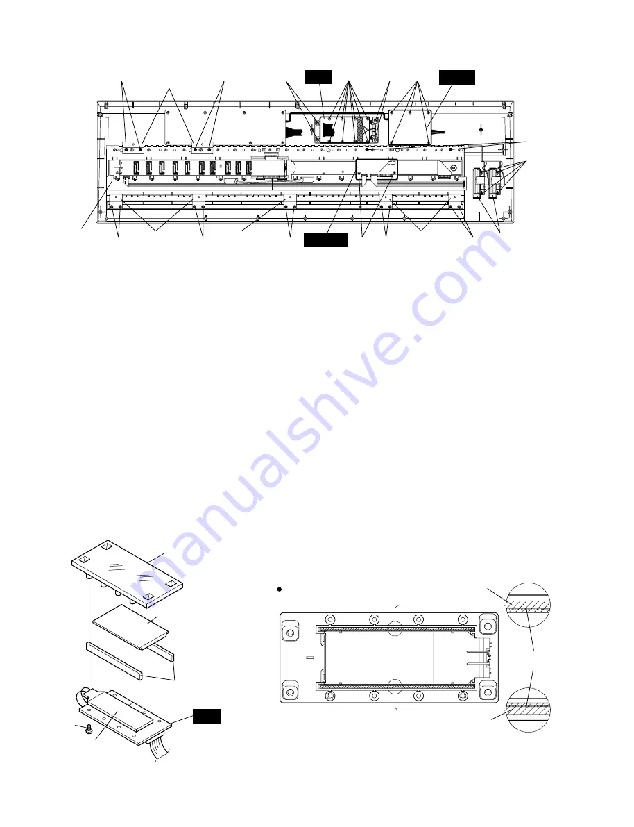
6-1 Remove the bottom cover assembly. (See procedure 1.)
6-2 Remove the shield box assembly. (See procedure 5-2.)
6-3 Remove the LC circuit board and the back light assembly. (See
procedure 5-4.)
6-4 Remove the two (2) rubber connectors from the LCD panel.
(Fig.5)
6-5 Lift the left end of the LCD first, and then remove it. (Fig.5)
6-6 Remove the four (4) screws marked [30A]. The LCD Panel can
then be removed. (Fig.4, 5)
*
When re-install the rubber connector, place it so that the
conductor faces the inside. (Fig.6)
VOL
MKS3
LC
[80]
[30A]
[30A]
[L60]
MKR angle
[60A]
[60A]
[40]
[40]
[40]
[30B] [40]
[40]
[100B]
[60B]
Keyboard Assembly
MKF angle
MKF angle
MKF angle
Wheel Assembly
Fig.4
[30A]:
Bind Head Tapping Screw-B
[30B]:
Bind Head Tapping Screw-P
[30B]:
Bind Head Tapping Screw-P
[40]:
Bind Head Tapping Screw-B
[60]:
Bind Head Tapping Screw-B
[L60]:
Bind Head Tapping Screw-P
[80]:
Bind Head Tapping Screw-B
[100B]: Bind Head Tapping Screw-B
3.0X8 MFZN2BL (EP600190)
3.0X8 MFZN2Y (EP600280) or
3.0X8 MFZN2BL (EP630220)
3.0X8 MFZN2BL (EP600190)
3.0X20 MFZN2BL (VJ999700)
3.0X8 MFZN2Y (EP600280)
3.0X8 MFZN2BL (EP600190)
3.0X8 MFZN2BL (EP600190)
Rubber Connector
Rubber Connector
Conductor side
Fig.6
Fig.5
LCD Panel
Rubber Connector
[L60]
Back Light Assembly
LCD
LC
LCD Panel
Summary of Contents for S03 voice editor
Page 4: ...S03 4 ...
Page 23: ...S03 23 B B Pattern side Pattern side DM 2NA V583600 4 LC 2NA V626840 LC Circuit Board ...
Page 27: ...S03 27 to MKS3 CN4 to MK L G G G G H H H H MK H Circuit Board Component side 2NA VV583900 ...
Page 34: ...S03 34 ...
Page 35: ...S03 35 ...
Page 36: ...S03 36 ...
Page 37: ...S03 37 ...
Page 38: ...S03 38 ...


