background image

For  Service  Engineer 

Service Information 

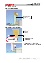
SI1604009E-002= S20, S10, M20, M10 and D10 installation procedures 

28/34 

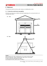
5.2    The effects caused by the slanted floor 

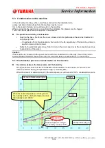
This section describes how the uneven floor affects the machine operation. 

The board transfer height of the YAMAHA standard machines should fall within 900 +/- 10mm, and the 
tolerance is 20mm. 

If the floor of the installation site is not in the condition that meets the specification, the production line 
cannot be aligned by the usual method. 

If the machine is equipped with the fixed type feeder bank, problems do not occur as long as the 
difference in height is in the adjustable range by the adjuster bolts. 

However, if the machine is equipped with the feeder exchange carriage, when the board transfer height 
does not fall within the specification (900+/- 10mm), it disables the feeder exchange carriage to be 
shared among the machines, which makes it difficult to manage the carriages. Make sure that all the 
machines can share the carriages. 

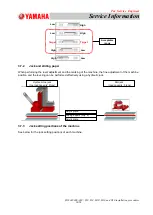
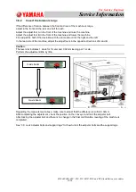
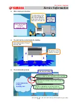
Even when the floor condition falls within the specification, if the whole floor is slanted, the board 
transfer height may need to be changed from 900mm. 

Note: 

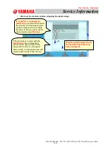
If the board transfer height falls within 900 +/- 10mm in the whole production line as shown in the figure 
below, and the reference machine is installed on the left end, adjust the machine height so that the board 
transfer height is to be approx. 910mm. 

<When the levelness of the floor falls within the specification (900+/- 10mm)> 


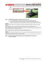
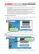
<When the levelness of the floor does not fall within the specification (900+/- 10mm)> 


Caution: 

When a machine needs to be installed with its transfer height out of specification, the feeder exchange 
carriage cannot be shared with other machines or other production lines. 
Make sure to gain the customer

’s approval when the transfer height needs to be set out of specification 

before aligning the production line. 


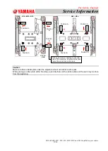
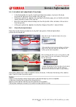
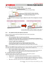
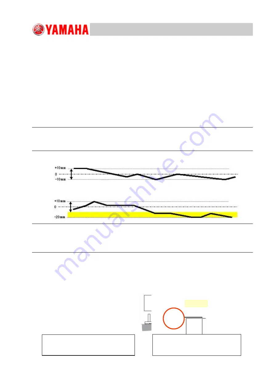
The effect on the leveling bolts 

If the floor of the installation site is not level, the leveling bolts on the lower side (of the floor) may come 
off and the thread of the leveling bolts cannot be inserted into the base properly, which disables the 
bolts secure the machine properly. 

On the higher side of the floor, the fixing nut of the leveling bolt interferes with the machine frame, and 
the levelness of the machine cannot be adjusted. 


Machine 

Machine 

-The leveling bolt comes off from the machine. 
-The leveling bolt cannot secure the machine 

properly. 


The levelness of the machine cannot be 
adjusted due to the interference between 
the machine and the leveling bolt. 

Summary of Contents for S20

Page 1: ...the current view of YAMAHA on the issues discussed as of the date of issuance As YAMAHA must respond to changing market conditions it should not be interpreted to be a commitment on the part of YAMAHA...

Page 2: ...Correction and adjustment of levelness 18 3 8 1 Check the X beam torsion 18 3 8 2 Case if the torsion is large 19 3 9 Lock adjuster bolts and support legs 20 4 Setup after installing the machine 22 4...

Page 3: ...able conductor cross section 3 5mm2 or more Leakage current 20mA or less Installation environment requirement Item Detail Remark Noise Meeting EN61000 6 2 standard Humidity 50 60 non condensing Temper...

Page 4: ...source and the air supply Make sure that the customer is informed of the specified capacity of the power source for the machine Make sure that the customer is informed of the specified diameter of th...

Page 5: ...e installation site must be 10 degrees C or less Rent a stove etc and gradually warm up the machine Carry in the machine after confirming that the base of the machine temperature rises 5 degrees C Cau...

Page 6: ...roblem later on Take some pictures of the damage Make sure to get the customer s permission before doing so Remove plastic wrapping from the machine After moving the machine to near the production lin...

Page 7: ...us Remark X axis 1 position LOCK X AXIS LF1 M220Y 00 BOLT HEX SOKET HEAD M4 L8 Qty 4 91312 04008 Y1 axis 1 position LOCK Y AXIS LE6 M260Y 00 BOLT HEX SOKET HEAD M5 L10 Qty 2 91312 05010 Y2 axis 1 posi...

Page 8: ...ark X axis 1 position LOCK X AXIS LF1 M220Y 00 BOLT HEX SOKET HEAD M4xL8 Qty 4 91312 04008 Y1 axis 1 position LOCK Y AXIS LE6 M260Y 00 BOLT HEX SOKET HEAD M5xL10 Qty 2 91312 05010 Y2 axis 1 position L...

Page 9: ...ark X axis 1 position LOCK X AXIS LF1 M220Y 00 BOLT HEX SOKET HEAD M4xL8 Qty 4 91312 04008 Y1 axis 1 position LOCK Y AXIS LE6 M260Y 00 BOLT HEX SOKET HEAD M5xL10 Qty 2 91312 05010 Y2 axis 1 position L...

Page 10: ...LOCK X AXIS LF3 M220W 00 BOLT HEX SOKET HEAD M5xL8 Qty 2 91312 05008 Y1 axis 1 position LOCK Y AXIS LE6 M260Y 00 BOLT HEX SOKET HEAD M5xL10 Qty 2 91312 05010 Y2 axis 1 position LOCK Y AXIS LF3 M220Y 0...

Page 11: ...east 2 pcs Dedicated jig PCB Required when connecting our machine to other manufacturer machines Steel ruler 1m or 60cm steel ruler If not having them approx 3m metal tape measure can be substitution...

Page 12: ...leted inform the customer to check the marking If not doing this and continuing marking the customer may point out that the marking is incorrect Step 2 Lower the hand lifter on the machine installatio...

Page 13: ...d level the X and Y directions temporarily Check if the positions to place the level vial are clean and there is no foreign object on the surface If it is contaminated clean it with waste cloth If the...

Page 14: ...e the fine adjustment of the machine position and the leveling can be performed effectively using a hydraulic jack 3 7 3 Jack setting positions of the machine See below for the jack setting positions...

Page 15: ...terfere with a jack When placing a rubber plate at the final step a jack interferes with a rubber plate and the work may be done from the beginning S20 M20 S10 M10 D10 Rubber plate If the equipment is...

Page 16: ...hydraulic toe jack from the outer cover side of the machine at the position B the cover is longer than the frame downward And when setting a wood plate between a jack and the machine frame make sure t...

Page 17: ...ack is raised Make sure not to push the machine excessively When pushing the machine push the lower side of the machine Install the machine to the position where the space between machines is less tha...

Page 18: ...fine adjustment If turned the adjuster bolt in order to adjust the torsion of X beam it influences the leveling of the machine base Therefore check the position again Caution There is a case that the...

Page 19: ...mount of the right and the left In the rear side of the machine adjust the adjust foots in the opposite directions of A and B Caution The level vial indicates 1 scale for 1meter and 0 02mm leaning per...

Page 20: ...the lock nut to tighten 4 adjuster bolts Caution When tightening the lock nut the transfer height rises by the amount of backlash of the screw Approx 0 5mm The specified value of the tightening torque...

Page 21: ...ke sure that one person checks the pressure intensity of the blots and lock the lock nut to prevent the variation When tightening the lock nut secure the adjuster bolts with a wrench and rotate the lo...

Page 22: ...ews and the nuts make sure to perform with the posture of Fig B If the weight locates the bottom Fig D the adhesive between GOM and the weight may peel off Balancer unit Monitor bracket Fig A The bala...

Page 23: ...ixing screws The screws are installed to the back of the monitor Use the screws and install the monitor to the monitor bracket BALANCER LE7 M131L 11 GOM LE7 M132M 00 Shockproof rubber 1 Remove the fix...

Page 24: ...llation procedures 24 34 4 3 Air and power connection 4 3 1 Connect the air and power to the machine Rod terminal with insulation NICHIFU TMEV TC3 5 11 The equivalent product is also available PE L3 W...

Page 25: ...the adjustment Step 3 Activate the vacuums of all heads Activate the vacuums of all heads by manual button and check that the measurement value of the manometer is 430Kpa or more If the measurement va...

Page 26: ...ach on the conveyors at the connecting part of the reference machine and the adjacent machine and check if the height of the conveyors is the same Adjustment when the transfer is not smooth and there...

Page 27: ...by suspending This section describes how to unload the machine by suspending such as using a truck with a unic The figure below is M20 Caution When using the arm make sure that the wires do not interf...

Page 28: ...fer height falls within 900 10mm in the whole production line as shown in the figure below and the reference machine is installed on the left end adjust the machine height so that the board transfer h...

Page 29: ...ite is not made of concrete reinforce the position on the floor where the legs of the machine are placed Consult with the experts who are familiar with the installation site When using the feeder exch...

Page 30: ...ical contact Defect in the electrical system e g Short circuit on the circuit board or at the connection part due to penetration of the water Caution If the machine is connected to the power source wi...

Page 31: ...he machine is almost the same as the outside air temperature after being exposed to the open air Outside air temperature 10 deg C Indoor temperature 20 deg C Humidity 60 Temperature of the machine 10...

Page 32: ...e the air conditioner to warm up inside the vehicle while transporting the machine to prevent the machine gets cooled down before being carried into the installation site 5 3 3 When condensation occur...

Page 33: ...between the mounter and the wrap to warm up the mounter and the air inside the wrap In this way the mounter can be warmed up effectively If the machine is covered with the plastic wrap the condensati...

Page 34: ...gineer Service Information SI1604009E 002 S20 S10 M20 M10 and D10 installation procedures 34 34 6 Revision history No Contents Note Date 000 First release June 14 2016 001 Addition of head fixing jig...

Reviews: