Reference Manual
Reference
98
Parameter
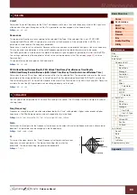
Q
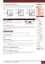
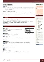
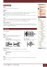
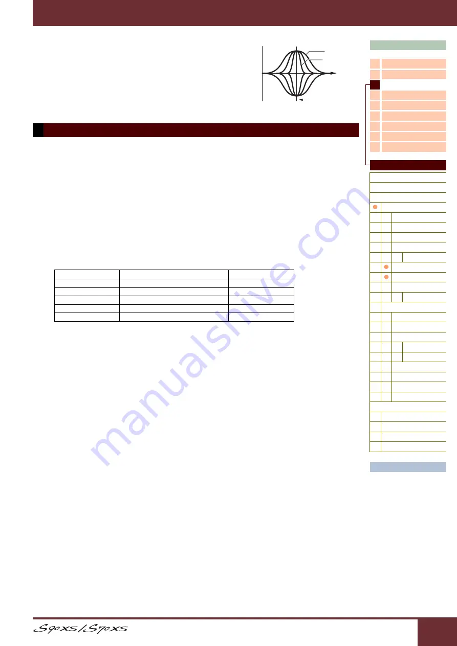
This varies the signal level at the “Freq” (Frequency) setting to create
various frequency curve characteristics. The higher the setting, the
smaller the bandwidth. The lower the setting, the greater the bandwidth.
Settings:
0.1 – 12.0
NOTE:
When the Shape parameters of the Low and High are set to “shelv,” the
“Q” parameters of Low and High are not available.
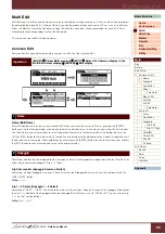
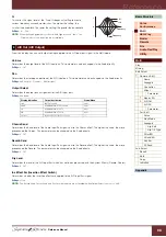
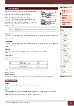
From this display, you can set output settings applied to the A/D Input part signal in the Multi mode.
Volume
Determines the output level of the A/D Input part. This parameter can be changed via the Knob directly.
Settings:
0 – 127
Pan
Determines the stereo pan position of the A/D Input part. This parameter can be changed via the Knob directly.
Settings:
L63 (far left) – C (center) – R63 (far right)
Output Select
Determines the output jack assignment for the A/D Input part.
Settings:
See below.
Chorus Send
Determines the Send level of the Audio Input Part signal sent to the Chorus effect. The higher the value, the more
pronounced the Chorus. This parameter can be changed via the Knob directly.
Settings:
0 – 127
Reverb Send
Determines the Send level of the Audio Input Part signal sent to the Reverb effect. The higher the value, the more
pronounced the Reverb. This parameter can be changed via the Knob directly.
Settings:
0 – 127
Dry Level
Determines the level of the A/D Input Part which has not been processed with the System Effects (Reverb, Chorus).
Settings:
0 – 127
Ins Effect Sw (Insertion Effect Switch)
Determines whether the Insertion effects are applied to the A/D Input Part signal.
Settings:
off, on
NOTE:
The Reverb Send, Chorus Send, and Dry Level parameters are not available when Output Select is not set to “L&R.”
6 A/D Out (A/D Output)
Display indication
Output destination
Stereo/Mono
L&R
OUTPUT L and R
Stereo
asL&R
ASSIGNABLE OUTPUT L and R
Stereo
asL
ASSIGNABLE OUTPUT L
Mono
asR
ASSIGNABLE OUTPUT R
Mono
vocoder
Insertion Effect of the Part 1 Voice
----
–
+
0
0.1
12.0
Frequency
Frequency

