For Service Engineer
Service Information
SI1705004E-00=SIGMA-G5SII Service Manual
107/273
* Adjustment Procedure
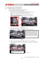
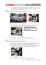
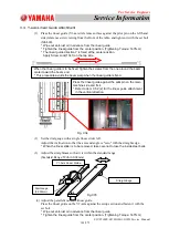
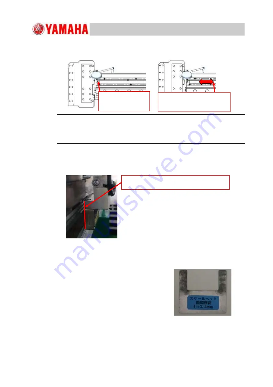
Place the dial gauge on the side of the linear scale and move the linear guide right
and left to check the center position. Move it to the position with the center value
and fix it.
Fig. C43
(3)
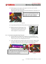
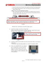
Attach the scale head set onto the scale head block.
When it is attached, fix it so that the scale head end surface is parallel with the block
end surface. If not, it might affect the adjustment after that.
(4)
Attach the assembled scale head block onto the main machine. When it is attached, fix
it temporarily.
* Put the scale head cable leading direction, etc., back to the original condition.
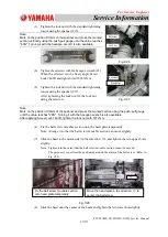
(5)
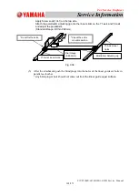
Put the scale head adjusting jig (t = 0.4mm)
between the scale head and linear scale and
loosen the temporarily tightened setscrews.
Then, tighten the setscrews at the position where
the jig can be pulled out with some difficulty.
(Refer to Fig. C45).
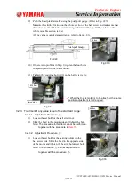
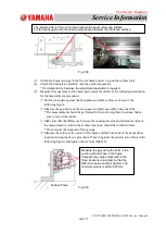
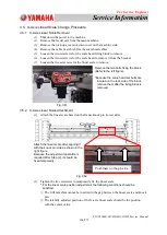
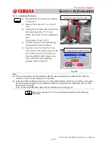
①
Place the dial gauge on the linear scale side surface. (Refer to the left figure).
②
Check the distance when the linear scale is moved right and left.
③
Find the center of the linear scale based on the measurement result in Step
②
. Fix
the linear scale at the position.
Touch the pick on the
linear scale end
surface.
Record the values when the
linear scale is moved right and
left.
Attach it so that the scale head side surface is
parallel with the scale head block.
Fig.C44
Fig.C45

