For Service Engineer
Service Information
SI1705004E-00=SIGMA-G5SII Service Manual
117/273
3.8. Y-Axis Scale Head Adjustment Procedure
3.8.1. Preparation of Adjusting Jig
For USB-422 DS15P
(1) Prepare the personal computer (Software for
adjustment
"
ST700 Scale MonitorHTI Specially
Designed Version
"
has beeninstalled), adjusting
jig unit.
(2) Connect the personal computer (hereinafter
called
"
PC
"
) and adjusting jig unit as follows.
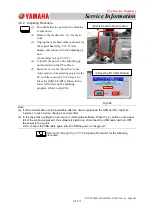
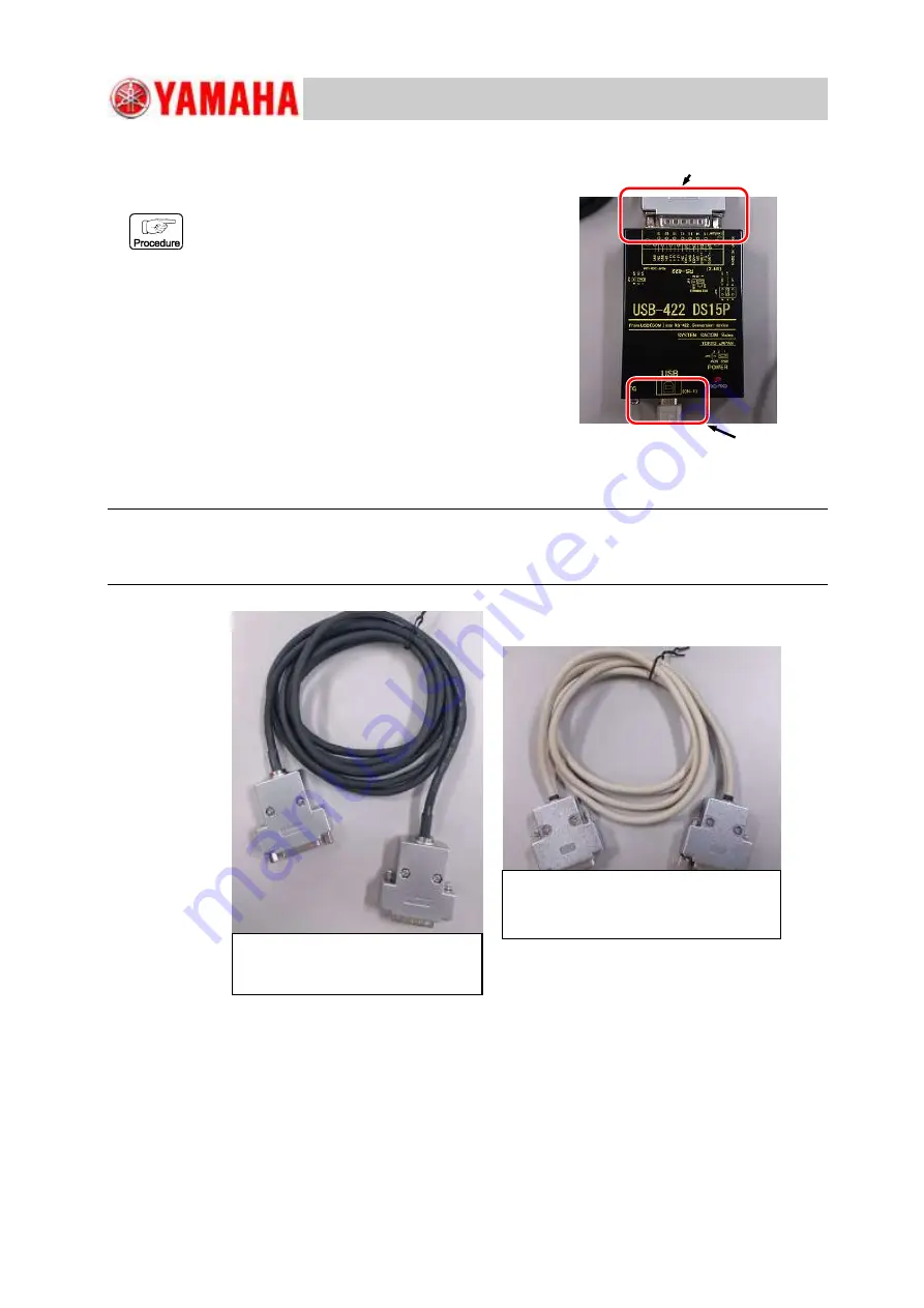
Connect the PC’s USB connector to the
adjusting jig D-SUB connector (in the frame in
Fig. C66-*1).
(3) There are two relay cables to connect to the
adjusting jig (Black and White cables).
Use the cable appropriate for the connector to be
connected (Refer to Fig. C67).
Note:
Take care so that no cables interfere with the machine because the beam is
operated in the adjustment operation. Also, because there are two types of cable, use them according
to the situation (Refer to Fig.C67).
Fig.C67
*2 Scale Head Side
*1 PC Side
Fig.C66
①
This cable is used to connect to
the scale head connector.
②
This cable is used to connect to the
connector on the relay panel.

