For Service Engineer
Service Information
SI1705004E-00=SIGMA-G5SII Service Manual
119/273
(6)
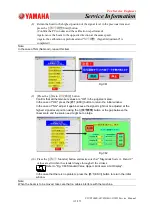
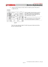
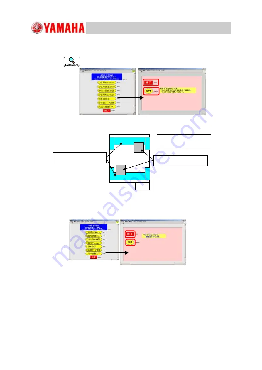
Press the [
⑤原点設定
] button.
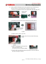
Press the Y-axis beam to be adjusted against the limit stopper (made of urethane)
outside the machine and press the [SET] button to set the origin.
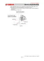
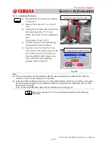
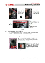
Refer to "Fig. C69" for the beam position of the Y-axis beam at the scale
origin setting operation.
Press the [
終了
(ESC)] button to return the initial window.
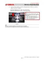
Fig.C70
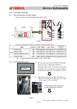
(7)
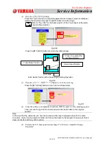
Press the [
⑦エラー履歴クリア
] button to clear the error log.
Press the [
終了
(ESC)] button to return to the initial window.
(8)
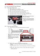
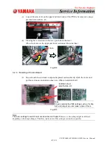
Close the software for adjustment and turn OFF the power to the adjusting jig unit.
Then, remove the jig from the head and return the head cable to the original
position.
Note:
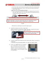
In the case that the cable ties, etc. have been released has been released except for the cable
connector, return it to the original condition and move the beam by hand again to make sure that it
does not interfere with any other section.
(9)
Perform the X/Y home position teaching of "4.18 Servo Amplifier Change
Procedure".
Fig.C69
Fig.C71
X-Axis Head Position
Y-axis Beam Position
* Press it to against the
urethane stopper.
Front Side
Each Beam Position at the Scale Origin Setting Operation

