For Service Engineer
Service Information
SI1705004E-00=SIGMA-G5SII Service Manual
123/273
4.1.3. Attachment of CPU1-BOX
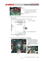
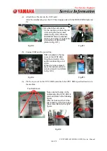
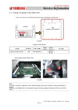
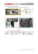
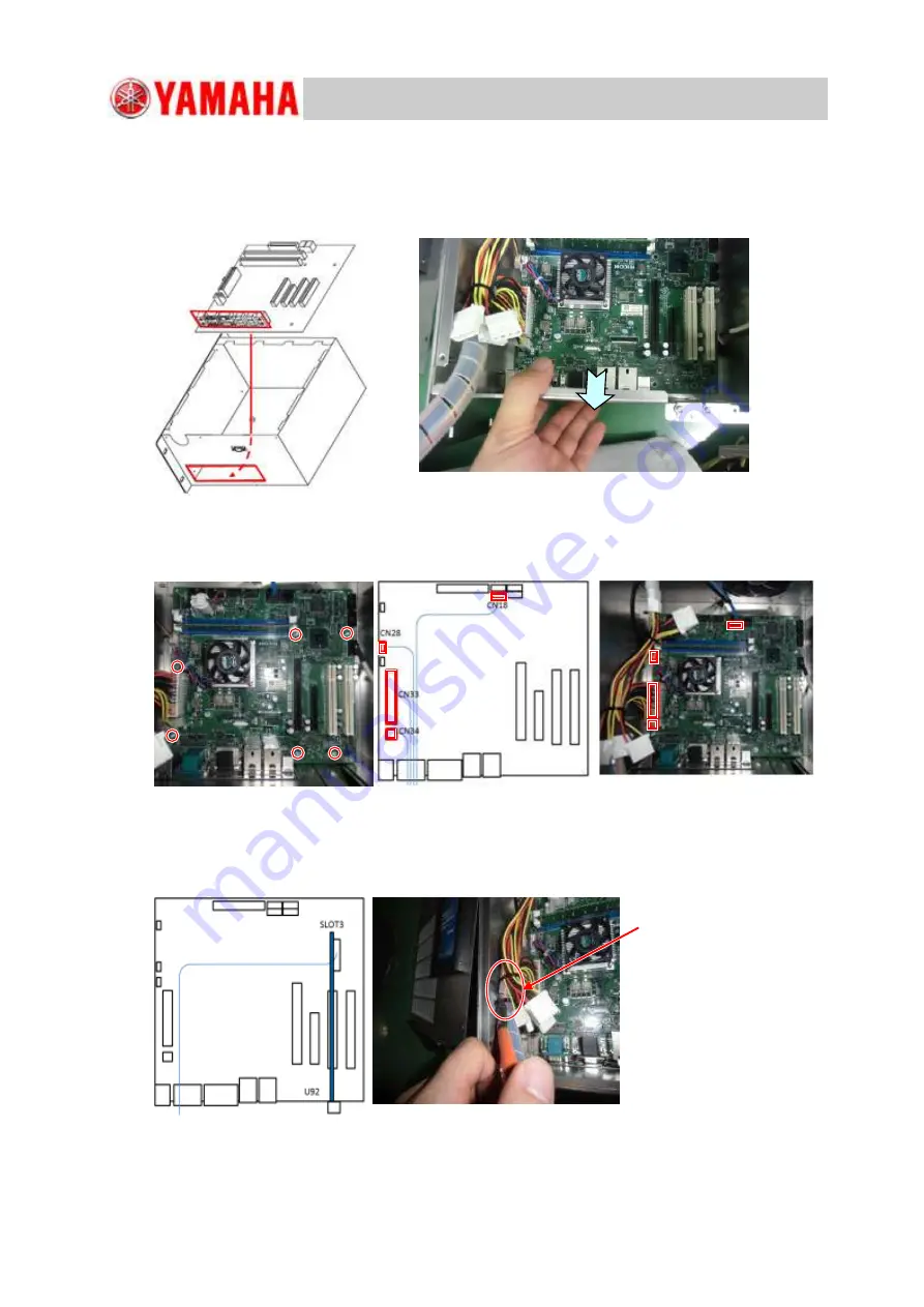
(1) Insert U91 (Control and Recognition Board) into CPU1 BOX as shown in the
following figure.
* Insert the connector section of U91, shown in a red frame, into the red-framed
section in the BOX.
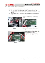
(2) Fix the six locations each in a red circle with a screw.
After fixing, connect the connectors in the sections specified in the following figure.
Insert the U92 board into the U91 board slot #2 and connect the power cable.
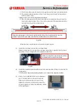
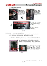
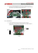
Fig.D8
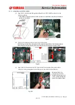
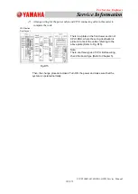
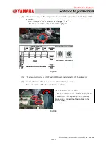
(3)
Insert the U92 board into the U91 board slot #2 and connect the power cable.
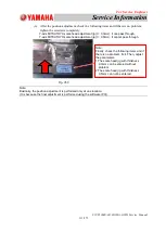
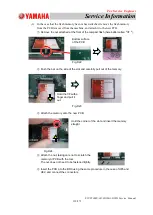
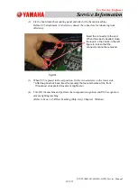
After the wiring arrangement, bind the power line cables with cable ties.
Because there is a
convex mount in the
location shown by a red
circle, collect and tie the
power line cables there.
Fig.D7
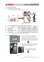
Fig. D9


