For Service Engineer
Service Information
SI1705004E-00=SIGMA-G5SII Service Manual
129/273
(2)
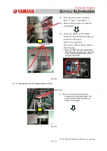
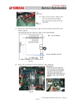
In the case that the flash memory has not been attached, remove the flash memory
from the PCB removed from the machine, and attach it to the new PCB.
①
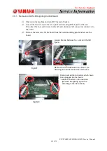
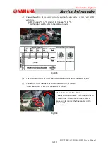
Remove the nut attached at the front of the compact flash (hereinafter called
"
CF
"
).
Fig.D22
②
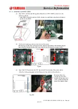
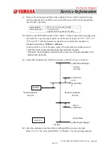
Push the bar on the side of the slot and carefully pull out of the memory.
Fig.D23
③
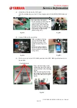
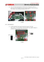
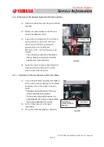
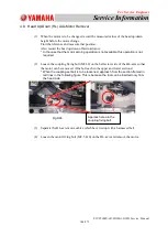
Attach the memory onto the new PCB
④
Attach the nut, taking care not to scratch the
memory or PCB with the tool.
The nut does not need to be fastened tightly.
⑤
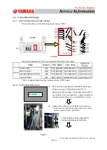
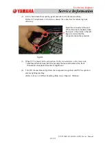
Insert the PCB into the BOX using the same procedure in the case of U85 and
U82, and connect the connectors.
Bottom surface
of the PCB
Hold the corner of the slot and insert the memory
straight.
Hold the CF with a
finger and pull it
out.
Fig.D24

