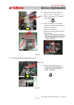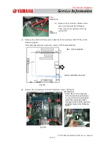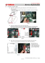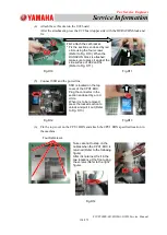
For Service Engineer
Service Information
SI1705004E-00=SIGMA-G5SII Service Manual
135/273
4.4.1. Multi-axis Board Change Procedure
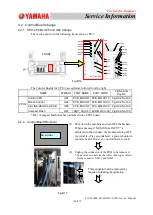
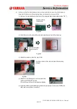
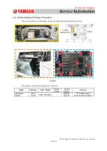
(1) Open the cover under the lower frame section (The breaker side is regarded as the
front side).
Remove the cover in the location framed by green lines.
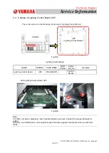
(2) Remove the cover for the electrical box section, which is framed by screws.
* When the cover is removed, take care not to damage the fiber cable.
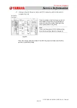
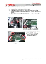
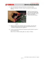
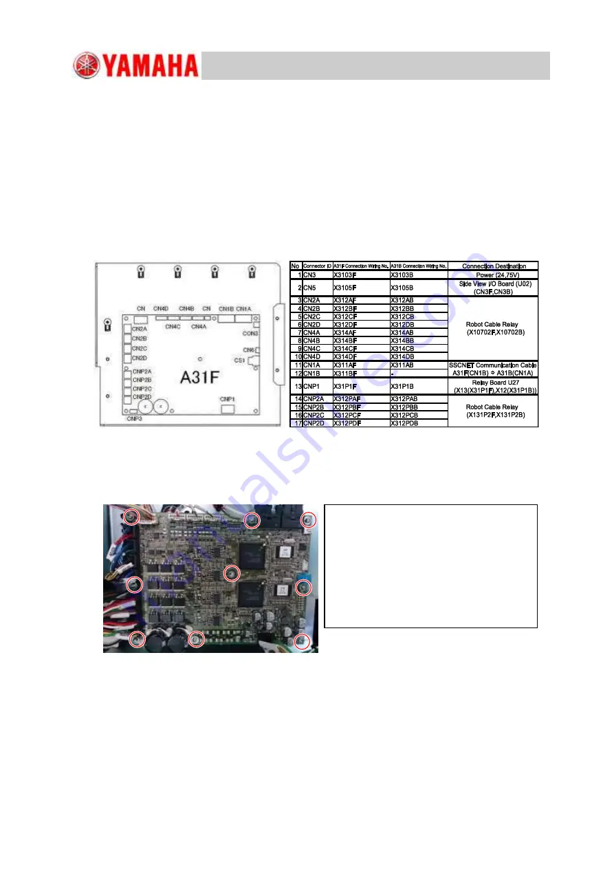
(3) Remove the cables connected to A31B and A31F.
* For the wiring arrangement, refer to the following figure.
Fig.D33
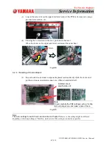
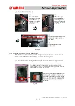
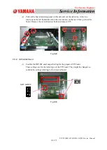
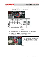
(4) Remove the screws fixing the nine locations on the upper surface of A31F and remove
the board.
Fig.D34
Screw fixing locations
Locations each shown in a red circle in the
left figure
(Remove the screws in the total nine
locations).
* When the screws are removed, the
board behind the A31F board fixed by
spacers is found can be accessible.
Remove it as well.

