For Service Engineer
Service Information
SI1705004E-00=SIGMA-G5SII Service Manual
136/273
(5)
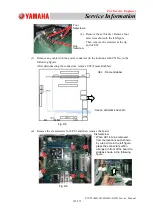
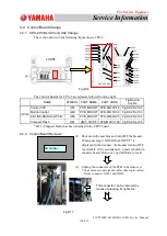
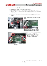
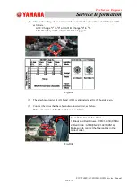
Change the setting of the rotary switch located on the side surface of A31F and A31B
as follows.
A31F: Change
"
1
"
to
"
0
"
and A31B: Change
"
0
"
to
"
1
"
.
* For the rotary switch, refer to the following figure.
Fig.D35
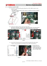
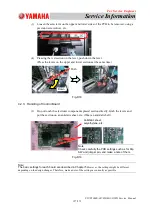
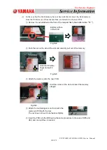
(6) The attachment order of A31F and A31B is alternated and fix the boards again.
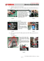
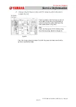
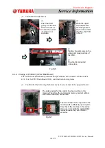
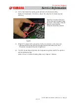
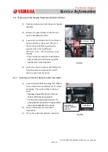
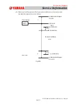
(7) Connect the wires that have been disconnected first, as before.
*The connections of the fiber cables are as follows.
Fig.D36
Fiber Cable Connection Order
1. Black and Red Arrows
:
CPU
⇒
A31B(CN1A)
2. Red Circle
:
A31B(CN2A)
⇒
A31F(CN1A)
Make sure to connect the fiber cables in the
correct order.

