For Service Engineer
Service Information
SI1705004E-00=SIGMA-G5SII Service Manual
141/273
(9)
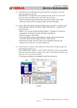
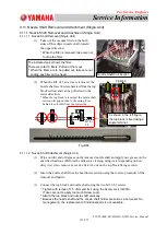
Remove the dial gauge and tighten the coupling setscrew with the specified torque.
After the adjustment, turn ON the servo for the NS-axis and XY-beam and perform
the "All Zero" operation.
Fastening Bolt
M2.5
×
L8, Screw Lock (1401B)
Fastening Torque
1 Nm (Newton)
(Tighten the bolt by hand at the field).
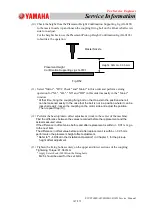
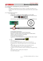
(10) Return to the "MOTOR" window of the "Maint." windows and set the dial gauge onto
the nozzle No. 1 position again and move the NS-axis at angles of "-25°","-20°", "0°"
"20°" and "25°" with the manual axis operation and confirm the cam delivery.
Standard Value Range:
/- 0.01 mm
In the case that it is out of the range, adjust it by loosening the coupling setscrew.
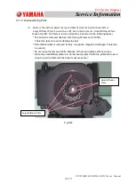
* After the check, remove the dial gauge from inside the machine.
* During the check operation, make sure not to move the XY beam absolutely. Only
NS-axis can be moved.
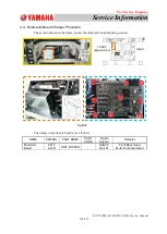
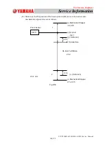
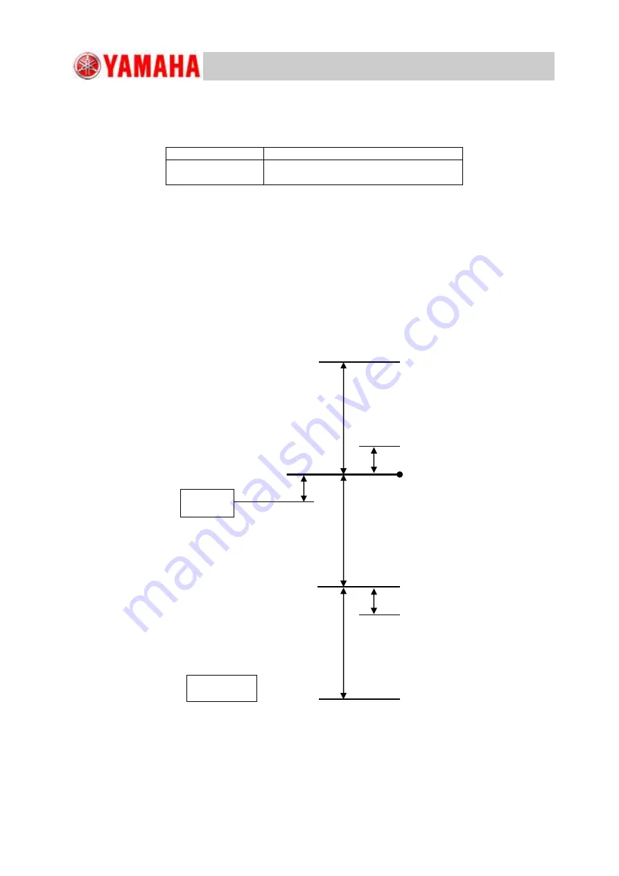
(11) Check that the upper/lower interlock positions on the NL-axis are as follows.
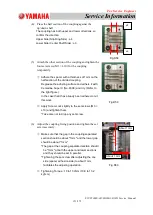
(12) After the adjustment, teach the [NL-Axis Origin Offset] and save the data.
Refer to "1.4.5.1 NL-Axis Origin Offset " in Chapter 1, for the teaching operation.
(-)
Mechanical Stopper
NL-Axis Zero
0.2 ± 0.2
NL-Axis Interlock
21.0mm
NL-Axis Full Stroke
(+) Mechanical Stopper
0.5mm
22.0±0.4mm
Unit : mm
B
0503
Fig.D44
-0.9+0.6
-0.9-0.35
(-)
Soft Limit
(+) Soft Limit
0
(
-
0.5)

