For Service Engineer
Service Information
SI1705004E-00=SIGMA-G5SII Service Manual
167/273
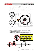
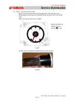
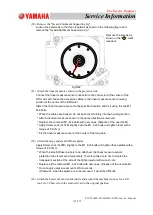
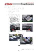
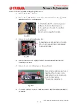
(20) Remove the "Head Attachment Supporting Jig".
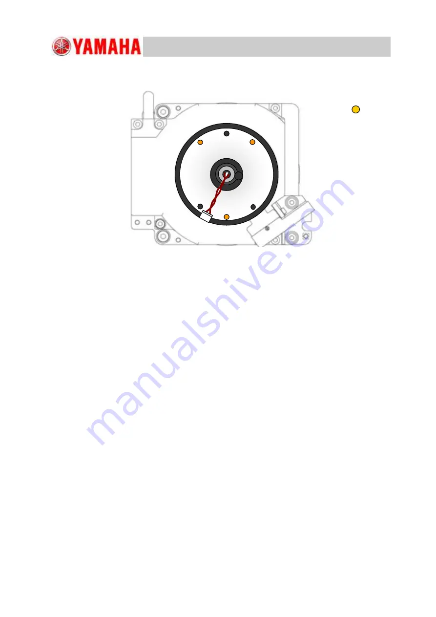
Loosen the setscrews in the three locations as shown in the following figure and
remove the "Head Attachment Supporting Jig ".
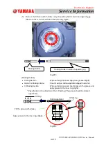
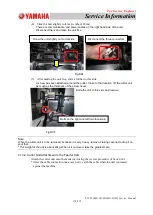
(21) Attach the linear measure sensor on the projector side.
Connect the linear measure sensor connector to the connector at the center of the
DD motor and house the excessive cables in the linear measure sensor housing
section at the center of the DD motor.
Attach the linear measure sensor to the specified location and fix it using the two M1.
6L4 bolts.
* When the cables are housed, do not push them forcibly into the housing section.
* Attach the linear measure sensor in the same direction as removed.
* Replace the removed M1. 6L4 bolts with new ones. (Dispose of the used bolts).
* Apply Screw Lock (1401B) slightly onto the M1. 6L4 bolts and tighten them with a
torque of 4.8 cN
m.
* Fix the linear measure sensor at the center of the long hole.
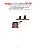
(22) Attach the large and small diffuser plates.
Apply Screw Lock (1401B) slightly to the M1. 6L4 bolts and tighten these plates with a
torque of 4.8 cN
m.
* When the small diffuser plate is to be attached, the linear measure sensor
protection tube is removed temporarily. Therefore, take care not to scratch the
transparent section at the side of the light projector with wrench, etc.
* Replace all the removed M1. 6L4 bolts with new ones. (Dispose of the used bolts).
* Do not apply excessive amounts of Screw Lock.
(Otherwise, when the plates are to be removed, it would be difficult).
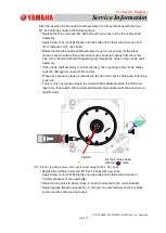
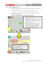
(23) Attach the head cover and check inside and around the machine (such as for a left
tool, etc.). Then, return the removed cart to the original position
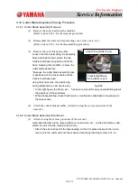
Fig.D82
Remove the screws as
shown in the " " mark
locations.

