For Service Engineer
Service Information
SI1705004E-00=SIGMA-G5SII Service Manual
176/273
4.16. Cutter Blade Assembly Change Procedure
4.16.1. Cutter Blade Assembly Removal
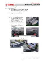
(1) Remove the cutter unit from the machine.
(Refer to Item 4.14.1, for the removal procedure).
(2) Disassemble the cutter unit (tape leading cover, side covers, etc.).
(Refer to Item 4.15.1, for the disassembling procedure).
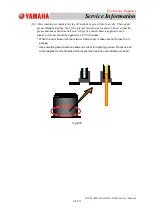
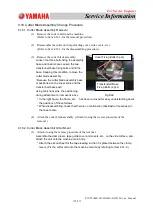
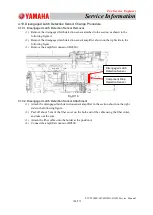
(3) Remove the cutter blade assembly.
Loosen the three bolts fixing the assembly
base and linear scale. Loosen the two
transfer belt base fixing bolts and lift the
base. Keeping this condition, remove the
cutter blade assembly.
*Because the cutter blade assembly base
is positioned on the linear scale and the
transfer belt base each
using two knock pins, the positioning
during attachment or removal is easy.
* In the right figure, the frame, etc., has been removed for easy understanding about
the positions of the setscrews.
* When disassembling, check that there is no malfunction (backlash or looseness) in
the linear scale.
(4) Attach the cutter blade assembly. (Attach it using the reverse procedure of the
removal.)
4.16.2. Cutter Blade Assembly Attachment
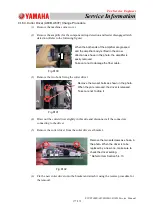
(1) Attach it using the reverse procedure of the removal.
Assemble the clamp lever, tape guide cover and covers, etc., on the side surface, and
attach the unit onto the machine main body.
* Attach the silicon sheet for the tape leading so that it is placed between the clamp
levers. (Fix the cutter unit onto the machine main body referring to Item 4.14.2.)
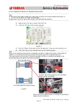
Fig.D99
Linear Fixing Bolts (3 pcs)
Transfer Belt Base
Fixing Bolts (2 pcs)


