For Service Engineer
Service Information
SI1705004E-00=SIGMA-G5SII Service Manual
198/273
(5)
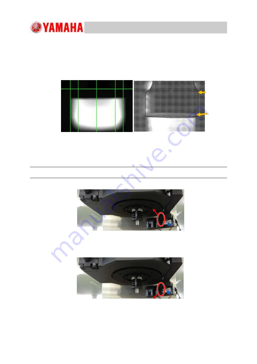
Make sure that the obtained HA09C image satisfies the following
"
i
"
and
"
ii
"
conditions.
ⅰ
. The measured value is between
"
0.900
"
and
"
1.234
"
.
ⅱ
. There is no white horizontal line on the nozzle like the NG (No Good) image.
If any of the above conditions is not satisfied, go to Step (7).
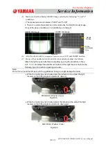
HA09C OK Image
HA09C NG Image
(6)
After the check work is completed, remove the HV82C and HA09C nozzles.
(7)
If any of the conditions in 4-(1) and (5) is not satisfied, adjust it as follows.
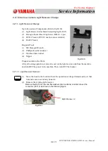
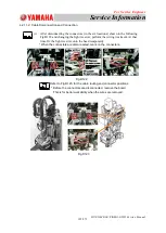
Attach the light receiver attachment adjusting jig using the procedure in Step
4.21.1.3 (1) and adjust the attachment position of the light receiver. Refer to the
following figure for definite adjusting procedure.
Note:
Do not turn around the DD-axis with the jig attached. Doing so might damage the head.
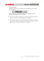
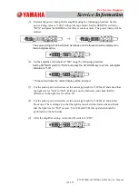
When the nozzle tip end is located over the reference line, adjust the light
receiver so that tilting angle is adjusted to upward.
When the nozzle tip end is located under the reference line, adjust the light
receiver so that tilting angle is adjusted to downward.
M2L8 Bolt + Washer (2 pcs)
M2L8 Bolt + Washer (2 pcs)
Fig.D127
Fig.D128
Fig.D129
Nozzle
Outline
White
Horizontal
Line

