For Service Engineer
Service Information
SI1705004E-00=SIGMA-G5SII Service Manual
44/273
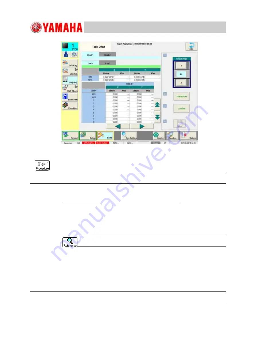
Fig. A37
Teaching Procedure
Glass Jig PCB Clamping Procedure
Note:
Unless the support jig and support pins are not removed, the glass jig PCB might be broken.
(1)
Make sure that nothing is attached on the backup table.
(2) Make sure that the PP data PCB size X is 280 mm or smaller. In the case of 280mm
or larger, change the pattern program to one for the PP data with the PCB size of
280 mm or smaller.
(3) Enable the debug mode and press the [Maint.] button in the operation window and
press the [Unit Adj.] button. Then, zero each of the "L-Conveyor", "Conveyor" and
"R-Conveyor" in the "Conveyor" tab sheet.
Refer to "Change Procedure to Debug Mode" for the procedure to transfer to
the debug mode.
(4) Perform the setting so that "619.1" is added to the SW data and "597.1" is deleted.
(5) Change the conveyor width.
Enter the value of "430" in the "Tgt Wd" text box and "0.3" in the "Clearance" text
box on the "CONVEYOR" tab sheet.
(6) Set the Z-clamp pressure to "0.1Mpa" so as not to break the glass jig PCB.
(7) Place the PEC recognition calibration jig onto the upstream side stopper position
manually.
Note:
Press the PEC recognition calibration jig reference onto the machine reference side manually.


