For Service Engineer
Service Information
SI1705004E-00=SIGMA-G5SII Service Manual
98/273
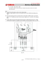
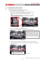
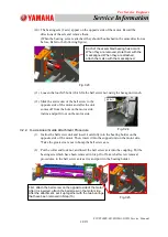
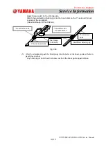
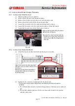
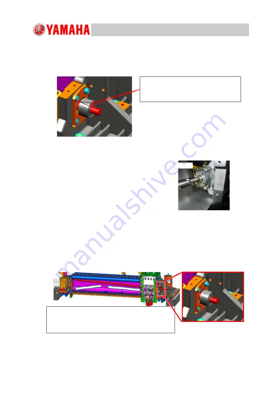
(10) The bearing sets (2 sets) appear on the opposite side of the motor. Record the
directions of the sets and remove them.
(When the bearing sets are attached, they should be attached in the same direction as
before. Refer to the following figure).
Fig. C23
(11)
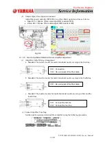
Loosen the four M5 bolts which fix the ball screw nut, using the hexagon wrench.
(12)
Slide the entire unit of the ball screw to the
opposite side of the motor and after the unit
comes off from the hole on the motor side,
incline and pull it out on the motor side.
3.2.2. X-axis Linear Guide Attachment Procedure
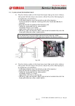
(1)
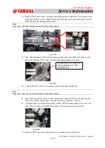
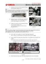
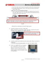
Incline the ball screw unit and insert it carefully into the bearing holder on the
opposite side of the motor. Then, insert it into the support unit on the motor side.
*
Take the greatest care not to bump the ball screw axis.
(2)
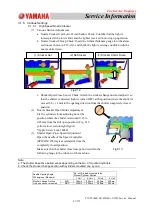
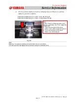
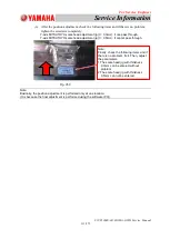
Put the collar and lock nut, and insert the ball screw axis into the coupling. Put the
bearing sets which have been removed in Step 10 of X-axis ball screw removal
procedures, in the ball screw axis as it is and put it in the bearing holder.
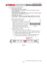
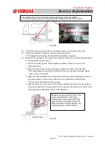
Each of the assembled bearing has a mark.
When they are removed, store them with the
mark aligned. When they are attached,
attach them also with the mark aligned.
②
①
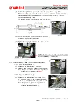
First, attach the ball screw on the opposite side of the motor.
After it is inserted, attach the ball screw on the motor side.
After the attachment, set it up together with the two bearings
that have been removed in Step (10).
Fig. C24
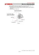
Fig.C25
M5 Bolt

