For Service Engineer
Service Information
SI1705004E-00=SIGMA-G5SII Service Manual
101/273
3.3. Y-axis Linear Guide Attachment
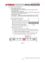
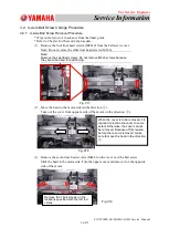
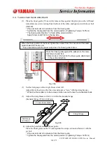
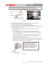
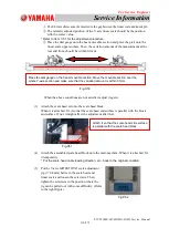
(1) Press the linear guide (Y1-axis) reference surface against the pilot pin on the left hand
side (reference side) viewing from the front of the table, and tighten it with the set bolt
(M6L20).
* Wipe out anti-rust oil in advance from the linear guide.
* Tighten the linear guide from the center position. (Tightening Torque: 14.7N.m)
* The linear guide direction Y is fixed at the center position.
Apply Screw Lock(1341) on the tap side.
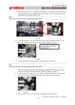
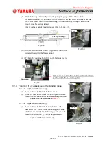
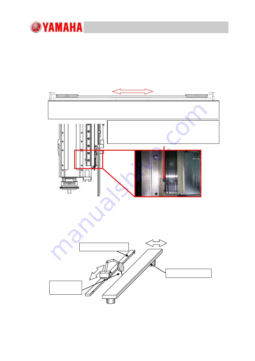
(2)
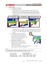
Set the dial gauge with a single linear slider left.
Adjust the inclination so that the axis end angle is
"
zero
"
with the straight edge.
* When the linear slider is to be removed, take care not to lose the inside steel balls.
(3)
Adjust the straightness so that it is within the standard range.
(Standard Range: Within 0.02mm)
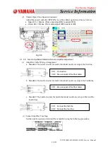
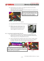
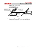
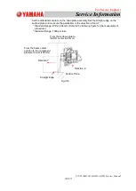
(4) Adjust the parallelism of the linear guide.
Press the linear guide on the Y2-axis against the setup section and fasten it with the
set bolt.
* Wipe out anti-rust oil in advance from the linear guide.
* Tighten the linear guide from the center position. (Tightening Torque: 14.7N.m)
Y1-Axis Linear Guide
Straight Edge
・
0
・
0
Dial Gauge
(0.002mm)
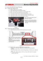
When the linear guide is to be fixed, tighten the screws from the one around the beam
center toward the beam end.
* This procedure avoids the beam warp when the linear guide is fixed.
Fig. C34
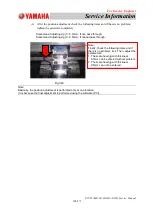
Fig.C35
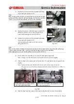
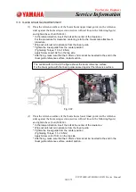
Press the linear guide against the pilot pin on the main
machine side and fix it.
* Refer to Item 3.5.2 (2) for the linear guide attachment
in the vertical direction.

