–37–
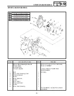
DRIVE CHAIN HOUSING
POWR
TR
NOTE:
INSPECTION
1. Measure:
14 link section
a
of the drive chain
Using a spring scale, pull on the drive chain
with 36 kg ( 80 lbs) of force
b
.
Out of specification
³
Replace the drive
chain.
Maximum 14 link drive chain
section length:
133.35 mm (5.25 in)
Limit 137.35 mm ( 5.41 in)
Measure the length between drive chain pin
1
and
15
as shown.
Perform this neasurement at two or three dif-
ferent places.
If replacement is necessary, always replace the
chain and the sprockets as a set.
2. Inspect
Drive chain
1
Stiffness
³
Clean and lubricate or replace.
Drive chain plates
2
Damage / wear
³
Replace the drive chain.
Cracks
³
Replace the drive chain.
INSTALLATION
During installation, pay attention to the following
point:
A
Make sure that the bearing seals face to-
wards the drive chain, as shown.
B
Properly install the rubber seal onto the drive
chain housing, making sure that these are no
gaps.
C
Be sure to install the spacers in their original
positions of the brake disc and jackshaft will
stick.
D
0.3 mm (0.012 in)
: ESSO beacon 325 grease or Aeroshell
grease #7A
Summary of Contents for SX500D
Page 1: ...SUPPLEMENTARY SERVICE MANUAL ...
Page 85: ... 81 CABLE ROUTING SPEC CABLE ROUTING 500 ...
Page 87: ... 83 CABLE ROUTING SPEC ...
Page 89: ... 85 CABLE ROUTING SPEC ...
Page 91: ... 87 CABLE ROUTING SPEC ...
Page 93: ... 89 CABLE ROUTING SPEC ...
Page 95: ... 91 CABLE ROUTING SPEC ...
Page 97: ... 93 CABLE ROUTING SPEC CABLE ROUTING 600 700 ...
Page 99: ... 95 CABLE ROUTING SPEC ...
Page 101: ... 97 CABLE ROUTING SPEC ...
Page 103: ... 99 CABLE ROUTING SPEC ...
Page 105: ... 101 CABLE ROUTING SPEC ...
Page 107: ... 103 CABLE ROUTING SPEC ...
Page 109: ... 105 CABLE ROUTING SPEC ...
Page 112: ...WIRING DIAGRAM ...
Page 114: ...WIRING DIAGRAM ...

