background image

131

Selecting the UtilityMode & Jobs

The utility mode and its various jobs are se-

lected in exactly the same way as in the voice, drum,
multi-play and sequencer edit modes. Press [UTIL-

ITY] to enter the utility mode; use the page access or
direct job number entry procedure to select jobs; use
the [ ] and [ ] cursor keys to select parameters
within a job display; and use me [DATA ENTRY]

control, [-1/NO] and [+1/YES] keys, or numeric and

[ENTER] keys to change values or settings. When

using the page access method, the MIDI and CARD

jobs are contained in subsets accessed by pressing

the [ENTER] key at the appropriate screen, and- ex-
ited by pressing the [EXIT] key.

Summary of Contents for SY55

Page 1: ...YAMAHA AUTHORIZED PRODUCT MANUAL MUSIC SYNTHESIZER ...

Page 2: ...YAMAHA MUSIC SYNTHESIZER ...

Page 3: ...ar to be the source of the interference you should try to correct the situation by using one or more of the following measures Relocate either the equipment or the electronic device that is being af fected by the interference Utilize power outlets for the professional music equipment and the device being affected that are on different branch cir cuit breaker or fuse circuits or install AC line fil...

Page 4: ...SY55 Music Synthesizer Operating Manual ...

Page 5: ... s samples are flexible tools that the musician can shape color and combine to create an original world of sound MAIN FEATURES Second generation 16 bit AWM2 Advanced Wave Memory technology for superior sound Versatile 1 2 or 4 element voice architecture and complex envelope generators for extensive sample layering capability Sophisticated dynamic filter system offers unlimited real time timbre var...

Page 6: ... 11 2 SELECTING AND PLAYING VOICES 13 3 THE MULTI PLAY MODE 19 4 RECORDING PLAYBACK WITH THE SEQUENCER 27 5 EDITING VOICES 35 REFERENCE VOICE EDIT MODE 50 DRUM EDIT MODE 92 MULTI EDIT MODE 104 SEQUENCER MODE 116 UTILITY MODE 130 ERROR MESSAGES 144 SPECIFICATIONS 147 INDEX 148 See these pages for local tables of contents 1 ...

Page 7: ...he connector not the cord 6 Clean With a Soft Dry Cloth Never use solvents such as benzine or thinner to clean the unit Wipe clean with a soft dry cloth 7 Always Use the Correct Power Supply The power requirements for the SY55 are clearly marked on the rear panel Make sure the specified mains voltage matches the voltage in your area before using the unit 8 Electrical Interference Since the SY55 co...

Page 8: ...n sequence while ac tually carrying out the procedures on your SY55 Once you ve gone through the entire TUTORIALS section in this way you should be familiar enough with the SY55 to need only the REFERENCE section in future What s In the The REFERENCE section is the nuts and bolts section of the manual REFERENCE Section individually describing each of the SY55 s many functions or jobs in detail The...

Page 9: ...er effects MASTER VOLUME Adjusts the volume of the sound delivered via the rear panel OUTPUT Control and PHONES jack SEQUENCER Keys Control the record play and measure selection functions of the internal Indicator sequencer INTERNAL CARD Select the data bank internal card or preset from which voices or and PRESET Keys multi play setups will be selected VOICE Key Indicator Selects the normal voice ...

Page 10: ...m edit mode when voice number 63 or 64 is selected the multi play edit mode if the multi play mode is selected or the sequencer edit mode if the sequencer mode is selected Also activates the compare function in certain edit modes allowing quick comparison of the original and edited voice or multi play setup UTILITY Key Accesses the SY55 utility functions including MIDI parameters master tuning tra...

Page 11: ... play drum and sequencer editing modes as well as in the utility mode PAGE and PAGE Keys JOB Key Allows fast direct access to any of the SY55 voice drum multi play and sequencer editing jobs SELECT Key Allows selection of voice elements and filters during voice editing or track record and mute assignments in the sequencer mode Numeric Keys The SY55 numeric keys allow direct selection of voices or ...

Page 12: ...TUTORIALS SECTION ...

Page 13: ...nd Setup Selection 20 MULTI PLAY Polyphony and Dynamic Note Allocation 20 Checking and Modifying MULTI PLAY Voice Assignments 20 Creating an Original MULTI PLAY Setup 22 Storing an Edited MULTI PLAY Setup 25 Conclusion 26 4 RECORDING PLAYBACK WITH THE SEQUENCER 27 The Sequencer Multi Play Interface 27 Realtime Recoding Replace Overdub 28 Step Recording 31 Playback 34 Conclusion 34 5 EDITING VOICES...

Page 14: ...t the SY55 to other MIDI devices be sure to use high quality MIDI cables of not longer than about 15 meters Power on Procedure 1 Make sure that both your sound system s volume control and the SY55 MASTER VOLUME control are turned almost all the way down prior to turning power on 2 Turn on the SY55 3 Turn on the sound system 4 Carefully adjust the SY55 MASTER VOLUME control and your sound system s ...

Page 15: ...r system Take a short break and enjoy the demos 1 Press and then release the SEQUENCER time and keys at the same 1 2 2 Press the ENTER key to start demo playback 3 Press the EXIT key when you want to stop demo playback Pressing EXIT a second time returns you to the mode the SY55 was in prior to the demo playback mode ...

Page 16: ... which you can store up to 64 voices that you create or load from an external memory card The INTERNAL voice bank is represented on the display by the letter I CARD The CARD memory bank is a YAMAHA MCD64 or MCD32 Memory Card or pre programmed voice card plugged into the SY55 DATA card slot on the front panel Memory cards are convenient for external storage and transportation of voices that you or ...

Page 17: ...ass BrassChime Piano Mist Xanadu WdBass Duo Drum Set 1 Drum Set 2 EL Number of elements sec page 35 No Name Comments P01 Piano Orthodox acoustic piano P02 Voyager Choir with sizzle Play long chords P03 Pro55Brass Fat analog brass pad P04 Elektrodes Mellow electric piano P05 Zaratustra Big orchestra Brass volume on MW P06 DawnChorus Breathy choir MW fades out breath P07 GX Dream A punchy voice remi...

Page 18: ...estra Light touch for string section only P45 VCO Lead Analog sawtooth lead voice P46 Spirit VCF Analog synth with big slow filter sweep P47 OZ Lead Soft synth lead P48 Get Lucky Fat square wave synth sound with detune on MW P49 Gamma Band Oriental percussion ensemble MW fades in metal drums and bells P50 Metal Reed Harmonica or accordion with after touch pitch bend P51 Modomatic Choir with big MW...

Page 19: ...lot and both banks of the card are properly formatted REFERENCE section page 138 pressing the CARD key alternately selects bank 1 in dicated by C on the display or bank 2 C on the display 3 The 1 NO and 1 YES keys can be used to select the desired voice within the current bank Holding the 1 NO and 1 YES causes continu ous scrolling in the specified direction Any voice can also be directly selected...

Page 20: ...example the SELECT HOLD key is pressed while a voice in the thirties is selected then pressing numeric key 1 will immediately select voice number 31 the 5 key will immediately call voice number 35 etc The hold mode can be released by pressing the SELECT HOLD key a second time 4 Play the selected voice via the SY55 keyboard If you don t get any sound at this point Make sure your sound system is tur...

Page 21: ...ces that essentially have a 61 element configuration Each element in this case corre sponds to a different key on a keyboard A range of high quality drum and percussion waveforms can be assigned to the different elements keys and handled as a single voice i e each key plays a different instrument within that drum set The drum set voices are particularly useful with the SY55 s MULTI PLAY mode and s...

Page 22: ...rgan Channel 3 voice Trumpet Channel 4 voice Saxophone Channel 5 voice off Channel 6 voice off Channel 7 voice off Channel 8 voice Drum Set 2 Channel 9 voice off Channel 16 voice off In addition to 16 PRESET MULTI PLAY setups including the one de scribed above 16 INTERNAL memory locations are provided for complete MULTI PLAY setups including voice to channel assignments individual voice volume not...

Page 23: ...e assigned The SY55 also has a RESERVED NOTE function that allows you to specify a minimum number of notes for each voice REFERENCE section page 110 Checking and Modifying Here s how you can see what voices are assigned to the various channels MULTI PLAY Voice As in any MULTI PLAY setup and change the voice assignments temporarily to signments try outalternativevoices 1 When you first select the M...

Page 24: ...er by pressing the key The underline cursor should now be located under the voice number 7 Use the 1 NO and 1 YES keys or numeric and ENTER keys to select the new voice for that channel or turn the channel off decrementing below voice number 01 selects off Different memory banks can be selected by using the MEMORY key 8 To assign a new voice to a different channel simply move the cursor back to th...

Page 25: ...GE and PAGE keys can be used to step forward and back ward through the jobs in any edit mode using job numbers is often the fastest way to access a specific editing job REFERENCE section page 52 This is the display for the MULTI PLAY EDIT mode voice assign ment function REFERENCE section page 108 5 The and cursor keys are used to move the cursor to the desired channel a channel number between CH1 ...

Page 26: ...the DATA ENTRY control 1 YES and 1 NO keys ornumeric and ENTER keys are used to set the desired volume A setting of 0 produces no sound while a setting of 127 produces maximum volume With the Jazz Quartet setup the relatively gentle wood bass sound tends to become buried under the other instruments so leave its volume setting at the maximum of 127 and lower the other three voices to about 110 Volu...

Page 27: ...ENTER keys are used to set the number of reserved notes 10 Press the PAGE key to move to the next MULTI PLAY EDIT mode job Pan REFERENCE section page 110 11 This job allows each individual voice in the setup to be panned to a different position in the stereo sound field you ll only hear this if you re using a stereo sound system fed by the SY55 OUTPUT R and L MONO jacks As always the and cursor ke...

Page 28: ...cter to be changed then use the DATA ENTRY control or 1 YES and 1 NO keys to select the desired charac ter Continue until the entire voice name has been programmed 16 Press MULTI to exit from the edit mode and return to the MULTI PLAY mode The reversed letter E that appears to the right of the voice number indicates that the MULTI PLAY setup has been edited Caution If you select a different MULTI ...

Page 29: ...ant because once you store all previous data in the target location is erased and completely replaced by the new data 4 Press 1 YES to confirm and actually execute the store operation or 1 NO to cancel Executing will appear on the display during store and Completed will appear briefly when the store operation is finished Your Jazz Quart MULTI PLAY setup has now been stored and can be recalled when...

Page 30: ...e separate multi play instrument Which track controls which instrument is determined by both the multi play setup MIDI channel assignments REF ERENCE section page 108 and the sequencer track channel assignments REFERENCE section page 119 Normally sequencer tracks 1 through 8 are assigned to the correspondingly numbered MIDI transmit channels so tracks 1 through 8 control the multi play instruments...

Page 31: ...derline cursor will be under the SONG song number parameter so you can use the DATA ENTRY control 1 NO and 1 YES keys ornumeric and ENTER keys to select the song number you want to record to 1 through 8 3 Press the RECORD key The RECORD key indicator will light and a display similar to the following will appear 4 Use the and keys to move the underline cursor to the parameter in and the upper right...

Page 32: ...T key is held When the desired record track is selected the corresponding instru ment in the current multi play setup will sound when the keyboard is played 7 Press the RUN key and start recording after a two measure count in The count in is indicated visually on the LCD by minus measure numbers e g recording will actually begin after a two measure count in from 8 to 0 if 4 4 time is selected 16 t...

Page 33: ...it possible to re record replace a section of a previously recorded track without affecting the data before and after the punch in section All operations are the same as for replace recording except that you must specify the measure numbers for the beginning and end of the punch in segment If you select punc instead of over or repl see step 4 above the display will appear as follows Move the curso...

Page 34: ...e step record edit display Step write input display line Each dash represents a 32nd beat Plus signs mark the beginning of each beat specified by the selected time signature The example below corresponds to a 1 4 4 4 time signature If an 8 beat time signature 1 8 8 8 were selected plus signs would appear every 4 32nd beats The cursor is placed under the appropriate beat of the display line by usin...

Page 35: ...ly after entering a note to tie that note to the next note entered The tie function is cancelled if you move the cursor between pressing the TIE key and entering the second note 5 When you ve selected the required note length play the note to be entered on the keyboard The entered note will appear as a diamond on the step record input display line The cursor will move to the beginning of the next ...

Page 36: ...a track by entering a program change command at the required point After moving the cursor to the point at which you want to change voices in the step record edit display press the PAGE key twice or the PAGE key once to select the program change display Select the desired bank and voice in the normal way then press the ENTER key The display will return to the step record edit display and a p will ...

Page 37: ... you press the SELECT key at any time in the sequencer play mode even while a sequence is playing the track mute display appears Then while holding the SELECT key the TR1 through TR8 keys nu meric keys 7 4 1 0 8 5 2 and respectively can be used to alternately engage or disengage muting for the corresponding track A dash appears in place of the track number when a track is muted Conclusion Now that...

Page 38: ... or 48 kilohertz 24 bit internal signal processing and high resolution 22 bit digital to analog converters The SY55 contains 2 megabytes of of sampled waveform ROM so you have a choice of 74 built in waveforms from which to construct voices PRESET WAVE LIST Elements and Voice Architecture Each SY55 voice is composed of one two or four elements The only limitation is that the maximum polyphony of t...

Page 39: ...as its own programmable 5 segment amplitude envelope generator so you can layer waveforms enveloped in different ways to create any number of unique sonic hybrids See page 64 of the REFERENCE section for a full description of the amplitude envelope generator parameters As an alternative to layering elements each element can be assigned to a different section of the keyboard for exotic split keyboa...

Page 40: ...lly unlimited range of dynamic filtering patterns can be produced See page 63 of the REF ERENCE section for details on the filter cutoff envelope generators Filter cutoff can also be controlled by the element s LFO low frequency oscillator Low pass and high pass filters can be combined to create a bandpass re sponse or both filters can be set for low pass operation each with a rolloff slope of 12 ...

Page 41: ...ilter cutoff control envelope generator bias and volume not to mention after touch pitch bias REFERENCE section pages 81 through 84 You also have direct access to 34 digital effect programs including reverb delay early reflection tone control and distortion each with several pro grammable parameters See page 86 of the REFERENCE section for details on the effects and their various parameters SY55 V...

Page 42: ...TUTORIALS SY55 Voice Parameter Chart Voice Name 39 ...

Page 43: ...SY55 Voice Parameter Chart Voice Name VeloChorus 40 ...

Page 44: ...dy selected press VOICE to select the VOICE PLAY mode 2 Use the INTERNAL 1 NO and 1 YES keys to select VOICE I01 3 Press EDIT COMPARE to enter the VOICE EDIT mode 4 Press the JOB key the numeric 4 and 2 keys and then the ENTER key to select voice edit job 42 Voice Initialize 5 The voice initialize function allows us to to create an initialized voice in which all parameters are set to their standar...

Page 45: ...the SY55 s 74 preset waveforms can be assigned to each The unavailable elements are represented by on the display The and cursor keys are used to move the cursor to the desired element EL1 or EL2 will appear in the upper right hand comer of the display and the DATA ENTRY control 1 YES and 1 NO keys or numeric and ENTER keys are used to assign the desired wave to the selected element The selected w...

Page 46: ...lets us set the lowest velocity value for a range of velocity values over which the element will produce output A little more explanation is in order Every MIDI note on message the MIDI message that is transmitted every time a note is played on a keyboard or other MIDI controller contains a velocity value that tells the tone generator how hard the note has been played The range of MIDI velocity va...

Page 47: ... markings next to the numeric 7 4 1 and 0 keys Also while the SELECT key is pressed any of the available elements can also be turned ON or OFF usually to hear how a single element in a multiple element voice sounds by pressing the corresponding EL ON OFF key the numeric 8 5 2 and keys An available element that has been turned OFF in this manner appears as a on the display Releasing the SELECT key ...

Page 48: ... and PAGE keys just as you can anywhere else When you re finished with the filter function subset return to the main function set by pressing the EXIT key Of course you can also access any of the filter jobs by pressing the JOB key and entering the appropriate job number The filter 1 or filter 2 envelope generator can be selected by holding the SELECT key and pressing the numeric 9 or 6 key respec...

Page 49: ...e 89 Storing an Edited Voice Now that you ve created your first original voice VeloChorus you ll want to store it to one of the SY55 s 64 internal voice memory loca tions or a memory card location 1 After exiting the edit mode by pressing the VOICE key press the STORE COPY key The following display will appear The voice number on the top line indicates the source setup i e the VeloChorus voice we ...

Page 50: ...re operation is finished Your VeloChorus voice has now been stored and can be recalled whenever needed Note Refer to the ERROR MESSAGES section on page 144 for infor mation on memory card related error messages Conclusion Well that s about it You ve learned the basics of getting around in the SY55 s play and edit modes Be sure to read the General Operation sections in the reference section for mor...

Page 51: ...REFERENCE SECTION ...

Page 52: ...9 NOTE SHIFT 59 DETUNE 60 LOW NOTE LIMIT 60 HIGH NOTE LIMIT 61 LOW VELOCITY LIMIT 61 HIGH VELOCITY LIMIT 62 PANNING 62 EFFECT BALANCE 63 OSCILLATOR MODE NOTE TUNE 63 AMPLITUDE ENVELOPE GENERATOR AEG MODE LEVEL RATE 64 AMPLITUDE ENVELOPE GENERATOR AEG RATE SCALING 66 AMPLITUDE ENVELOPE GENERATOR AEG LEVEL SCALE BREAKPOINT 66 AMPLITUDE ENVELOPE GENERATOR AEG LEVEL SCALE OFFSET 66 SENSITIVITY VELOCIT...

Page 53: ...FILTER RESONANCE VELOCITY SENSITIVITY MODULATION SENSITIVITY 77 ELEMENT INITIALIZE 79 CONTROLLER PITCH BEND RANGE 81 CONTROLLER AFTER TOUCH PITCH BIAS 81 CONTROLLER RANDOM PITCH RANGE 81 CONTROLLER AMPLITUDE MODULATION 82 CONTROLLER PITCH MODULATION 82 CONTROLLER CUTOFF MODULATION 83 CONTROLLER CUTOFF FREQUENCY CONTROL 83 CONTROLLER EG BIAS CONTROL 84 CONTROLLER VOLUME CONTROL 84 EFFECT TYPE OUTPU...

Page 54: ...g To step backward through the voice edit job list Hold for continuous scrolling In some cases a display screen accessed by the PAGE and PAGE keys will actually be a doorway to a separate list of jobs relating to that function In the voice edit mode the FILTER CON TROLLER and EFFECT jobs are of this type When Filter is selected for example press ENTER will appear on the bottom line of the display ...

Page 55: ... others contain several that must be selected using the and cursor keys In many cases the and keys arc used to select one of the available elements in a multi element voice The value of a selected parameter is adjusted using the DATA ENTRY control the 1 NO and 1 YES keys or the numeric and ENTER keys When using the numeric keys first enter the desired value in one two or three digits the value wil...

Page 56: ...lable elements can also be turned ON or OFF usually to hear how a single element in a multiple element voice sounds by pressing the cor responding EL ON OFF key the numeric 8 5 2 and keys An available element that has been turned OFF in this manner appears as a on the display Releasing the SELECT key returns the display to the current function Edit Compare Operation Normally when you play a voice ...

Page 57: ...m using the DATA ENTRY control or 1 YES and 1 NO keys If the element number ap pears in reverse the voice does not use that element and no data is available For Filter Copy the editbuf setting allows copying parameters from filter 1 to filter 2 or vice versa when copying within the same ele ment e g EL1 EL1 In this case the filter to be copied to must be selected prior to pressing STORE COPY key b...

Page 58: ...y on the display while the data is being copied then Com pleted will appear for a few seconds when the copy operation has been successfully completed 3 Use the 4 Next move the cursor to the multi or voice num and cursor keys to move to the Multi Voice parameter and select Multi if you want to copy the effect parameters from a multi timbral setup or Voice if you want to copy the effect parameters f...

Page 59: ...VOICE EDIT MODE 57 ...

Page 60: ...es you can play at the same time Mode Polyphony 1 element mode 16 notes 2 element mode 8 notes 4 element mode 4 notes The tutorial goes into further detail concern ing the use of the multi element modes Refer to Tutorial page 35 37 42 AWM WAVE SELECTION Summary Assigns a preset or card wave to each active voice element Settings P01 P58 preset voices P59 P74 preset drums C01 max C99 card voices Pro...

Page 61: ...each element makes it simple to set up the optimum balance or mix between ele ments Overall volume adjustment can be used to match the the overall level of different voices Refer to Tutorial page 42 NOTE SHIFT JOB 4 Summary Individually shifts the pitch of each ac tive element up or down in semitone steps Settings 64 63 Procedure The and cursor keys are used to select the element to be note shifte...

Page 62: ...e and cursor keys are used to select the element for which the low note limit is to be set EL1 EL2 EL3 or EL4 will appear in the upper right hand comer of the dis play Unavailable elements are represented by on the display The DATA ENTRY control or 1 YES and 1 NO keys are used to set the low note limit The low note limit can also be set by press ing the ENTER key KBD will flash on the display and ...

Page 63: ...ements are represented by on the display The DATA ENTRY control 1 NO and 1 YES keys or numeric and ENTER keys are used to set the low veloc ity limit The low velocity limit can also be set by pressing the ENTER key KBD will flash on the display and then a key on the keyboard at approximately the desired velocity Details Every MIDI NOTE ON MESSAGE the MIDI message that is transmitted every time a n...

Page 64: ...or keys are used to select the element for which the pan position is to be set EL1 EL2 EL3 or EL4 will appear in the upper right hand corner of the display Unavailable elements are represented by on the display The DATA ENTRY control 1 NO and 1 YES keys or numeric and ENTER keys arc used to set the pan posi tion The upper line of the display also shows a graphic representation of the stereo sound ...

Page 65: ...T TYPE OUT PUT LEVEL on page 85 EFFECT EFFECT PARAMETERS on page 86 Utility mode EF FECT on page 133 OSCILLATOR MODE NOTE TUNE JOB12 Frequency Mode Summary Determines whether the AWM wave for the selected element is reproduced in the normal variable pitch or fixed pitch mode Settings norm fix Procedure If the Frequency Mode Frq Mode on upper LCD line parameter is not already se Details Normally yo...

Page 66: ...s to a 75 64 cent change in pitch The entire tuning range is therefore 75 64 x 127 i e 64 63 incre ments almost 150 cents Since 100 cents equals one semitone the tuning range is approxi mately one and a half semitones A setting of 0 produces normal pitch A3 440 Hertz Please note that this parameter is used to in dividually tune different elements within a voice Overall tuning control is provided b...

Page 67: ...orms to pass unaffected In this case the R1 parameter is replaced by the HT Hold Time parameter The HT parameter determines the length of time between the beginning of the envelope and the point at which the envelope begins to move to wards L2 Level 2 at R2 Rate 2 as shown below For the level parameters a setting of 0 corresponds to the lowest possible level no sound while a setting of 63 produces...

Page 68: ... scaling breakpoints to be set at any notes between C 2 and G8 for the selected element Settings C 2 G8 Procedure Use the and cursor keys to select the desired breakpoint BP1 BP2 BP3 and BP4 from left to right then use the DATA ENTRY control or 1 YES and 1 NO keys to set the breakpoint note The breakpoint can also be set by pressing the ENTER key KBD will flash on the display and then the key on t...

Page 69: ...ired degree of velocity sensitiv ity Details Plus settings produce higher output level in response to higher velocity values i e the harder a key is played the louder the sound The maximum setting of 7 produces the maximum level variation in response to ve locity changes Minus settings produce the opposite effect lower level in response to higher velocity A setting of 0 results in no level variati...

Page 70: ... OSCILLATOR LFO WAVEFORM SPEED DELAY PHASE on page 69 LOW FREQUENCY OSCILLA TOR MODULATION DEPTH AMPLITUDE PITCH CUTOFF on page 70 CONTROL LER functions from page 81 to page 84 Pitch Modulation Sensitivity Summary Determines the sensitivity of the se lected element to pitch modulation vibrato ef fects applied via appropriate controllers Settings 0 7 Procedure Use the and cursor keys to select the ...

Page 71: ...O and 1 YES keys or numeric and ENTER keys to set the desired LFO speed Details 0 produces the slowest LFO speed and 99 produces the fastest LFO speed Refer to SENSITIVITY VELOCITY AMPLI TUDE PITCH MODULATION page 67 Procedure Use the and cursor keys to select the Speed parameter Use the DATA EN Delay Summary Sets the delay time between the begin ning of a note and the beginning of LFO opera tion ...

Page 72: ...D parameter is not already selected Details A 0 setting produces no modulation while a setting of 127 produces maximum modula tion Amplitude modulation produces a periodic variation in the volume of the sound thus creat ing a tremolo effect Please note that the amplitude modulation sensitivity parameter see page 68 must also be set to an appropriate value before amplitude modulation can be applied...

Page 73: ...h envelope gen erator for the selected element Settings L0 L1 L2 L3 and RL parameters 64 63 R1 R2 R3 and RR parameters 0 63 Procedure Use the and cursor keys to select the various rate and level parameters in turn L0 Rl L1 R2 L2 R3 L3 RR and RL using the DATA ENTRY control 1 NO and 1 YES keys or numeric and ENTER keys to set the value of each The arrow symbols and that appear at either end of the ...

Page 74: ... or 1 YES and 1 NO keys to select the desired range PEG Rate Scaling Summary Allows the overall pitch envelope gen erator rate for the selected element to be varied across the entire pitch range Settings 7 7 Procedure Use the and cursor keys to Details Plus settings produce a longer overall envelope time for the low notes and a shorter en velope time for the high notes The maximum 7 setting produc...

Page 75: ...f FILTER TYPE CUTOFF MODE JOB 22 Type LPF Filter Response Summary Determines the response of the selected filter Settings Filter 1 FL1 THU LPF HPF Filter 2 FL2 THU LPF Procedure If the Type parameter is not already selected use the and cursor keys to select it Use the DATA ENTRY control or 1 YES and 1 NO keys to select the desired filter response Filter 1 or Filter 2 can be selected by holding the...

Page 76: ...f the selected filter Settings 0 127 LPF 0 114 HPF Procedure Use the and cursor keys to select the Cutoff parameter Use the DATA EN TRY control 1 NO and 1 YES keys or numeric and ENTER keys to select the desired cutoff frequency Filter 1 or Filter 2 can be selected by holding the SELECT key and pressing the numeric 9 or 6 key respectively Details Lower cutoff values produce a lower cutoff frequenc...

Page 77: ...ial page 37 45 FILTER CUTOFF ENVELOPE GENERATOR below FILTER CUTOFF ENVELOPE GENERATOR JOB 23 Summary All parameters within this function de termine the shape of the cutoff envelope gen erator for the selected filler This function is only available if the Mode parameter page 63 is set to EG or EGVA Settings L0 L1 L2 L3 L4 RL1 and RL2 parameters 64 63 R1 R2 R3 R4 RR1 and RR2 parameters 0 63 meters ...

Page 78: ...es the greatest envelope length variation across the pitch range Minus settings produce the opposite effect a shorter low note envelope and longer high note envelope A setting of 0 results in no enve lope length variation Refer to FILTER CUTOFF ENVELOPE GEN ERATOR page 75 FILTER LEVEL SCALING BREAKPOINT JOB 25 Summary Allows four separate cutoff envelope generator level scaling breakpoints to be s...

Page 79: ... its maximum of 63 When different offsets are set for adjacent breakpoints the level varies accordingly and smoothly between the breakpoints Refer to FILTER LEVEL SCALING BREAK POINT on page 76 FILTER CUTOFF EN VELOPE GENERATOR page 75 cursor keys to FILTER RESONANCE VELOCITYSENSITIVITY MODULATION SENSITIVITY JOB 27 Resonance Summary Determines the degree of resonance of filter 1 and filter 2 Sett...

Page 80: ...y of the filter 1 and filter 2 cutoff frequency to modulation ap plied via the LFO and appropriate controllers Settings 7 7 Procedure Use the and select the Modulation Sensitivity parameter Mod Sens Use the DATA ENTRY control 1 NO and 1 YES keys or numeric and EN TER keys to set the required degree of modula tion sensitivity Details Plus settings produce higher cutoff frequen cies in response to m...

Page 81: ...is useful if you want to begin programming an element from scratch Refer to VOICE INITIALIZE page 90 Jobs AWM wave selection Volume Note shift Detune Low note limit High note limit Low velocity limit High velocity limit Panning Effect balance Oscillator mode note tune AEG mode level rate AEG rate scaling AEG level scalebreakpoint AEG level scale offset Sensitivity LFO waveform speed delay phase LF...

Page 82: ...eakpoint Filter level scaling offset Filter resonance velocity sensitivity modulation sensitivity InitializedValues L0 0 Range 2oct Type THU L0 0 R2 0 R4 0 RR2 0 0 BP1 C1 OFS1 0 Resonance 0 R1 63 L2 0 RL 0 R scale 0 Cutoff 127 R1 0 L2 0 L4 0 RL2 0 BP2 G2 OFS2 0 Vel sens 0 L1 0 R3 63 Vel SW off Mode LFO L1 0 R3 0 RR1 0 BP3 E4 OFS3 0 Mod sens 0 L3 0 L3 0 RL1 0 BP4 C6 OFS4 0 80 ...

Page 83: ...ired after touch pitch bias range Details Each increment represents a semitone A setting of 0 produces no pitch variation A setting of 12 allows a maximum pitch vari ation of one octave up while a setting of 12 allows a maximum pitch variation of one octave down corresponding to after touch key pressure CONTROLLER RANDOM PITCH RANGE JOB 31 Summary Sets the amount of random pitch vari ation produce...

Page 84: ...itude modulation will function Refer to SENSITIVITY VELOCITY AMPLI TUDE PITCH MODULATION page 67 keys to select the CONTROLLER PITCH MODULATION JOB 33 Summary Assigns a controller to and sets the maximum depth of pitch modulation applied by the LFO Settings CTL Control Number Parameter 0 120 AT RNG Range Parameter 0 127 Procedure Use the and CTL or RNG parameter then use the DATA ENTRY control 1 N...

Page 85: ...ate value before cutoff modulation will function Refer to FILTER RESONANCE VELOCITY SENSITIVITY MODULATION SENSITIV ITY page 77 keys to select the CONTROLLER CUTOFF FREQUENCY CONTROL JOB 35 Summary Assigns a controller to and sets the range of cutoff frequency control Settings CTL Control Number Parameter 0 120 AT RNG Range Parameter 0 127 Procedure Use the and CTL or RNG parameter then use the DA...

Page 86: ...meric and ENTER keys to set the selected parameter as required Details The CTL parameter corresponds to MIDI control numbers Standard controller as signments are noted in the upper right hand cor ner of the display CONTROLLER VOLUME CONTROL JOB 37 Summary Assigns a controller to and sets the range of volume control Settings CTL Control Number Parameter 0 120 AT MIN Minimum Parameter 0 127 Set the ...

Page 87: ...b Reverse Gate 19 FB E R 20 FB Gate 21 FB Rvs 22 Dly1 Rev 23 Dly2 Rev 24 Tunnel 25 Tone 1 26 Dly1 T1 27 Dly2 T1 28 Tone 2 29 Dly1 T2 30 Dly2 T2 31 Dist Rev 32 Dst Dly1 33 Dst Dly2 34 Dist Procedure If the Type parameter is not already selected use the and cursor keys to se lect it Use the DATA ENTRY control 1 NO and 1 YES keys or numeric and ENTER keys to select the desired effect Details Each eff...

Page 88: ... 1 50 miliseconds Sets the doubling delay HPF Thru 160 1000 Hertz Rolls off attenuates the low frequency content of the signal above the set frequency The HPF is OFF when set to THRU LPF 1 25 12 kilohertz Thru Rolls off attenuates the high frequency content of the signal above the set frequency The LPF is OFF when set to THRU 13 Doubler 2 9 Delay Time 0 1 300 milliseconds Sets the delay time FB De...

Page 89: ...rse Gate Room Size 0 5 3 2 Sets the separation between reflections Higher values produce greater separation between reflections and therefore the effect of a bigger room LPF 1 25 12 kilohertz Thru Rolls off attenuates the high frequency content of the signal above the set frequency The LPF is OFF when set to THRU FB Gain 0 99 Determines the amount of feedback returned to the input of the effect pr...

Page 90: ...Balance 0 100 Sets the amount of reverb in relation to dis tortion A setting of 0 produces distortion only while a setting of 100 produces dis tortion plus maximum reverb 50 produces an approximately even balance between the distortion and reverb sound 32 Distortion Delay 1 33 Distortion Delay 2 Time 0 1 300 milliseconds Sets the delay time FB Gain 0 99 Determines the amount of feedback returned t...

Page 91: ...ECALL JOB 41 Summary Recalls the last voice edited from the SY55 edit buffer Settings None Procedure After selecting the VOICE Edit Re call display press the ENTER key Sure will appear on the upper line of the display Press the 1 YES to initialize or 1 NO to cancel the initialize operation Completed will appear briefly when the recall operation is finished Details Even if you ve exited the voice e...

Page 92: ...amming a voice from scratch Refer to Tutorial page 42 ELEMENT INITIAL IZE page 79 Jobs Voice mode AWM wave selection Total volume Note shift Detune Low note limit High note limit Low velocity limit High velocity limit Panning Effect balance Oscillator mode note tune AEG mode level rate AEG rate scaling AEG level scale breakpoint AEG level scale offset Sensitivity LFO waveform speed delay phase LFO...

Page 93: ...pitch modulation Controller cutoff modulation Controller cutofffrequency control Controller EG bias control Controller volume control Effect type outputlevel Effect time LPF delay Voice name Initialized Values L0 0 Range 2oct Type THU L0 0 R2 0 R4 0 RR2 0 0 BP1 C1 OFS1 0 Resonance 0 2 0 0 CTL 12 CTL 1 CTL 1 CTL 12 CTL 2 CTL 14 Type 1 Time 2 6 sec INIT VOICE R1 63 L2 0 RL 0 R scale 0 Cutoff 127 R1 ...

Page 94: ... Function 94 The Effect Copy Function 95 JOBS PARAMETERS 96 AWM WAVE SELECTION 96 VOLUME 96 NOTE SHIFT 97 TUNE 9 7 ALTERNATE GROUP 9 8 PANNING 98 EFFECT BALANCE 99 VOLUME CONTROL 100 EFFECT TYPE OUTPUT LEVEL 100 EFFECT EFFECT PARAMETERS 101 DRUM SET VOICE NAME 101 DRUM SET VOICE RECALL 101 DRUM SET VOICE INITIALIZE 103 92 ...

Page 95: ...equirements Keys C1 through C6 are initially programmed with the following voices for P63 and P64 Voice 64 Drum Set 2 Voice 63 Drum Set 1 Selecting the Drum Edit Mode Jobs Edit Compare The drum edit mode and its various jobs are se lected in exactly the same was as in the voice edit mode the only difference being that a drum voice must be selected before the edit mode is engaged Sec Selecting the ...

Page 96: ...ate key on the master keyboard 3 Press the STORE COPY key The following dis play will appear 5 When the drum element to and from which the data is to be copied have been properly selected press the ENTER key Sure will appear on the top line of the LCD 6 Press the 1 YES key to confirm and actually execute the copy operation or 1 NO to cancel Completed will appear for a few seconds when the copy ope...

Page 97: ...serted in the DATA card slot the C or card bank 5 Press the ENTER key Sure will appear on the top line of the LCD 6 Press the 1 YES key to confirm and actually execute the copy operation or 1 NO to cancel Executing will appear briefly on the display while the data is being copied then Com pleted will appear for a few seconds when the copy operation has been successfully completed 7 When the copy o...

Page 98: ...so be turned off un assigned The off setting can be selected by decrementing below the lowest numbered wave Refer to Tutorial page 18 35 VOLUME JOB 2 Summary Allows the volume of individual drum elements to be adjusted as well as the overall volume of the current drum voice Settings 0 127 Procedure Select the drum element to be edited C1 C6 by pressing the appropriate key on the keyboard It is als...

Page 99: ...oice the note shift function can be used to create pitched sets of tom toms or other instruments TUNE JOB 4 Summary Allows each individual drum clement to be tuned over approximately a 150 cent range Settings 64 63 Procedure Select the drum clement to be edited C1 C6 by pressing the appropriate key on the keyboard It is also possible to select the drum element to be edited by moving the cursor to ...

Page 100: ...lose the hi hat before the open hi hat sound ends by playing the closed hi hat key PANNING JOB 6 Summary Determines the position in the stereo sound field in which the sound from each drum element will be heard left to right Settings 31 31 Procedure Select the drum element to be edited C1 C6 by pressing the appropriate key on the keyboard It is also possible to select the drum element to be edited...

Page 101: ...s selected and edited using the EFFECT functions described on page 86 Refer to EFFECT TYPE OUTPUT LEVEL on page 85 EFFECT EFFECT PARAMETERS on page 86 VOLUME CONTROL JOB8 Summary Assigns a controller to and sets the range of volume control for the current drum voice Settings CTL Control Number Parameter 0 120 AT MIN Minimum Volume Parameter 0 127 Procedure Use the and keys to select the CTL or MIN...

Page 102: ...y Sets the level of the selected drum voice effect in relation to the direct no effect sound Settings and operation are exactly the same as in the voice edit mode refer to EFFECT TYPE OUTPUT LEVEL on page 85 EFFECT EFFECT PARAMETERS JOB 10 Summary Accesses the individual programmable parameters for the selected drum voice effect Settings and operation are exactly the same as in the voice edit mode...

Page 103: ... SET VOICE RECALL JOB 12 Summary Recalls the last drum voice edited from the SY55 edit buffer Settings None Procedure After selecting the DRUM Edit Re call display press the ENTER key Sure will appear on the upper line of the display Press the 1 YES to initialize or 1 NO to cancel the initialize operation Completed will appear briefly when the recall operation is finished Details Even if you ve ex...

Page 104: ...appear on the upper line of the display Press the 1 YES to initialize or 1 NO to cancel the initialize operation Completed will appear briefly when the initialization is finished Details When Drum Initialize is executed the drum voice parameters are initialized to the following values The drum voice initialize function is useful if you want to begin programming a new drum set voice from scratch ...

Page 105: ...DRUM EDIT MODE 103 ...

Page 106: ...The Channel Copy Function 106 The Effect Copy Function 107 JOBS PARAMETERS 108 VOICE SELECTION 108 VOLUME 108 NOTE SHIFT 109 TUNE 109 RESERVED NOTE 110 PANNING 110 EFFECT LEVEL 111 EFFECT SOURCE 111 EFFECT TYPE OUTPUT LEVEL 112 EFFECT EFFECT PARAMETERS 112 MULTI NAME 113 MULTI RECALL 113 MULTI INITIALIZE 114 104 ...

Page 107: ... hand if only one voice is being played the SY55 s Dynamic Note Alloca tion feature allows 16 notes to be played simulta neously by that one voice even if 16 voices are assigned The SY55 also has a RESERVED NOTE func tion that allows you to specify a minimum number of notes for each voice Selecting the Multi Edit Mode Jobs Edit Compare The multi edit mode and its various jobs are se lected in exac...

Page 108: ... dis play will appear Next select the channel from which the pa rameter data is to be copied by using the DATA ENTRY control 1 NO and 1 YES keys or numeric and ENTER keys The number of the selected channel will appear to the right of the bottom LCD line 4 When the channels to and from which the data is to be copied have been properly selected press the ENTER key Sure will appear on the top line of...

Page 109: ...to the multi or voice number parameter by pressing the key and select the multi play setup or voice from which the parameter data is to be copied by using the DATA ENTRY control 1 NO and 1 YES keys ornumericand ENTER keys The INTER NAL CARD or PRESET key can be used to select the P preset or I voice bank if nec essary or if a properly formatted memory card is inserted in the DATA card slot the C o...

Page 110: ... page 23 Procedure Use the and cursor keys are Or if you have selectd a card multi play setup use the PRESET or CARD key to select the P preset or C card voice bank for each channel as necessary internal voices cannot be selected for card multi play setups By decrementing below the lowest voice P01 or I01 the assignment for the current chan nel can be turned off Details The bank character P or I o...

Page 111: ...can be used to trans pose a voice to its most useful range or to create harmony intervals between different voices in a multi play setup TUNE JOB 4 Summary Allows each individual voice to be tuned over approximately a 150 cent range Settings 64 63 Procedure The and cursor keys arc used to select the voice channel to be tuned The DATA ENTRY control 1 NO and 1 YES keys or numeric and ENTER keys are ...

Page 112: ...he piano to 3 and all but two of the remaining instruments to 1 The remaining two instruments set to 0 will be the ones that don t sound when a full comple ment of 16 notes is received Please keep in mind the fact that the SY55 can produce a maximum of 16 notes simultane ously no matter how this function is set The total number of reserved notes set for all chan nels should not exceed 16 Refer to ...

Page 113: ...5 EFFECT EFFECT PARAME TERS on page 86 EFFECT SOURCE JOB8 Summary Determines whether the current multi play setup will have its own effect settings or the effect parameters of one of the assigned voices will be applied Settings multi CH1 CH16 Procedure Use the DATA ENTRY control 1 NO and 1 YES keys or numeric and ENTER keys to select the desired setting Details When multi is selected independent e...

Page 114: ...ummary Sets the level of the selected multi effect in relation to the direct no effect sound Settings and operation are exactly the same as in the voice edit mode refer to EFFECT TYPE OUTPUT LEVEL on page 85 EFFECT EFFECT PARAMETERS JOB 10 Summary Accesses the individual programmable parameters for the selected multi effect Settings and operation arc exactly the same as in the voice edit mode refe...

Page 115: ...I RECALL JOB 12 Summary Recalls the last multi play setup edited from the SY55 edit buffer Settings None Procedure After selecting the MULTI Edit Re call display press the ENTER key Sure will appear on the upper line of the display Press the 1 YES to initialize or 1 NO to cancel the initialize operation Completed will appear briefly when the recall operation is finished Details Even if you ve exit...

Page 116: ...pear briefly when the initialization is finished Details When Multi Initialize is executed the multi parameters are initialized to the following val ues The multi initialize function is useful if you want to begin programming a multi timbral setup from scratch Jobs Initialized Values Voice selection Volume Note shift Tune Reserved note Panning Effect level Effect source Effect type output level Ef...

Page 117: ...MULTI EDIT MODE 115 ...

Page 118: ...s JOBS PARAMETERS SEQUENCER PLAY RECORD MODES MEASURE TEMPO TIME SIGNATURE CLICK SELECT SYNC SELECT TRACK TRANSMIT CHANNEL RECORD CHANNEL RECORD FILTER MIDI CONTROL SEQUENCER EDIT MODE MIXDOWN QUANTIZE DELETE INSERT COPY ERASE REMOVE EVENT SONG NAME SONG PROGRAM SONG CLEAR 122 122 123 124 124 125 126 127 127 128 116 ...

Page 119: ...ethods The sequencer edit mode can be exited at any time by pressing the EXIT key All basic sequencer record and playback opera tions have been described in detail in RECORD ING PLAYBACK WITH THE SEQUENCER in the tutorial section of this manual The play and record mode jobs listed in the fol lowing pages can be accessed from either the se quencer play or record standby modes by using the standard ...

Page 120: ... to sound only during re cording the rec play setting causes the metro nome to sound during both recording and play back and the always setting causes the metro nome to sound all the time even when the sequencer is not running The last setting al ways allows the metronome to be used for key board practice The volume of the click metronome sound can be adjusted via the rear panel CLICK VOL UME cont...

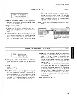
Page 121: ...l the data from each sequencer track will be transmitted on Settings Track 1 8 Channel 1 16 Details The track transmit channel assignments can normally be left at their default settings i e track 1 channel 1 track 2 channel 2 etc This means that there is an easy to follow one to one correspondence between the sequencer tracks and the receive channels of your multi play setups This function becomes...

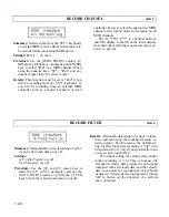
Page 122: ...er such as a master keyboard or wind RECORD FILTER JOB 6 Summary Independently turns recording of veloc ity and after touch data on or off Settings A T After Touch on off Vel Velocity on off Procedure Use the and cursor keys to select the A T or Vel parameter and use the DATA ENTRY control or 1 NO and 1 YES keys to turn the selected parameter on or off Details After touch data tends to be quite vo...

Page 123: ...anted interference from external MIDI de vices connected to the SY55 and or to prevent the SY55 sequencer from affecting operation of the external equipment Refer to Page 24 of separate MIDI DATA FOR MAT Summary Turns the sequencer MIDI control func tions on or off Settings on off Procedure Use the DATA ENTRY control or 1 NO and 1 YES keys to turn MIDI control on or off Details When this parameter...

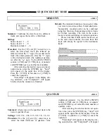
Page 124: ...r the sign Use the DATA ENTRY control 1 NO and 1 YES keys or numeric and ENTER keys to select the track numbers After selecting the desired source and desti nation tracks press the ENTER key Sure will appear on the upper line of the display Press the 1 YES to mixdown or 1 NO to cancel the operation Executing will appear on the display dur ing mixdown and Completed will appear briefly when the mixd...

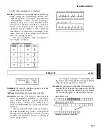
Page 125: ...n Executing will appear on the display dur ing delete and Completed will appear briefly when the delete operation is finished Details It s important to remember that a delete op eration affects all tracks simultaneously and that measures following the deleted range are moved back to take the place of the deleted measures Delete M004 006 Measure 4 through 6 deleted Summary Deletes the specified mea...

Page 126: ...ric and ENTER keys to select the measure numbers After selecting the desired source and desti nation measures press the ENTER key Sure COPY JOB5 ter upper line beginning source measure left most parameter lower line end source measure center parameter lower line or destination measure rightmost parameter lower line Use the DATA ENTRY control 1 NO and 1 YES keys or numeric and ENTER keys to se lect...

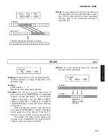
Page 127: ...ettings Track number 1 8 Beginning and end measure numbers TRACK 1 TRACK 1 Procedure Use the and cursor keys to select the track leftmost parameter beginning measure center parameter or end measure rightmost parameter Use the DATA ENTRY control 1 NO and 1 YES keys or numeric and ENTER keys to select the track and meas ure numbers After selecting the desired track and meas ures press the ENTER key ...

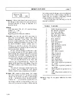
Page 128: ...meric and ENTER keys to select the control change number to be removed After selecting the desired event track and measures press the ENTER key Sure will appear on the upper line of the display Press the 1 YES to remove or 1 NO to cancel the op eration Executing will appear on the display dur ing remove and Completed will appear briefly when the remove operation is finished Details PB stands for P...

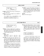
Page 129: ...ll appear when the corresponding song number is later selected or the sequencer mode is selected and the corresponding song number is the first to appear Summary Creates a program for the currently se lected song number that loads a specified multi play setup or voice from the internal preset or card bank when the same song is later selected in the sequencer play mode Settings Mode on off Multi M ...

Page 130: ...ignature New Song 120 4 4 Summary Clears the currently selected song from memory Settings None Procedure After selecting the SONG Clear dis play press the ENTER key Sure will ap pear on the upper line of the display Press the 1 YES to clear or 1 NO to cancel the opera tion Executing will appear on the display dur ing clear and Completed will appear briefly when the clear operation is finished 128 ...

Page 131: ...SEQUENCER MODE 129 ...

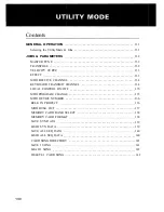
Page 132: ...AMETERS MASTER TUNE TRANSPOSE VELOCITY CURVE EFFECT MIDI RECEIVE CHANNEL KEYBOARD TRANSMIT CHANNEL LOCAL CONTROL ON OFF MIDI PROGRAM CHANGE MIDI DEVICE NUMBER BULK IN PROTECT MIDI BULK OUT MEMORY CARD BANK SELECT MEMORY CARD FORMAT SAVE SYN DATA LOAD SYN DATA SAVE ALL SEQ DATA LOAD ALL SEQ DATA CARD SONG DIRECTORY SAVE 1 SONG LOAD 1 SONG DELETE 1 CARD SONG 1 3 0 ...

Page 133: ...e page access or direct job number entry procedure to select jobs use the and cursor keys to select parameters within a job display and use me DATA ENTRY control 1 NO and 1 YES keys or numeric and ENTER keys to change values or settings When using the page access method the MIDI and CARD jobs are contained in subsets accessed by pressing the ENTER key at the appropriate screen and ex ited by press...

Page 134: ...ys or numeric and ENTER keys are used to set the desired degree of transposition TRANSPOSE JOB 2 Details A setting of 12 for example transposes down by one octave a setting of 4 trans poses up by a major third Refer to NOTE SHIFT pages 59 97 and 109 Details Each tuning increment corresponds to a 75 64 cent change in pitch The entire tuning range is therefore 75 64 x 127 i e 64 63 incre ments almos...

Page 135: ...sensitivity and different players have individual prefer ences This function lets you select the velocity curve that best suits your keyboard controller and playing style Try each one out to find the one you like best EFFECT JOB 4 Details This function completely turns the system effect processor off or on so when it is turned off no effects are applied to any voices or multi play setups Refer to ...

Page 136: ...DATA EN TRY control or 1 NO and 1 YES keys to set as required The numeric and ENTRY keys can also be used to select the channel number KEYBOARD TRANSMIT CHANNEL JOB 6 play setup is selected however the MIDI trans mit channel setting also determines which of the setup s voices is played via the SY55 keyboard Refer to Tutorial page 20 Details Make sure that the SY55 MIDI receive channel is either se...

Page 137: ...ectors on your keyboard controller will not cause the corresponding SY55 voice or multi play setup to be selected MIDI PROGRAM CHANGE JOB 8 external MIDI tone generator or other device from the SY55 keyboard without playing the internal tone generator turn local control off One possibility is to drive the SY55 tone genera tor system from the internal sequencer while independently playing a separat...

Page 138: ...elow Make sure that the SY55 de vice number is matched to that of other devices in your system with which such data transfers will take place Refer to ERROR MESSAGES page 144 MIDI BULK OUT page 137 BULK IN PROTECT JOB 10 Summary Enables or disables bulk data reception Settings off on Procedure The DATA ENTRY control or 1 YES and 1 NO keys are used to select off or on Details When this function is ...

Page 139: ...ponding PRESET multi play setup The P and I banks are switched using the PRESET or INTERNAL key The int or pre setting that appears after the highest memory number causes transmission of the entire INTERNAL int or PRESET pre multi play bank Procedure Use the and cursor keys to The voice setting allows transmission of individual or complete banks of voice data Select I01 through I64 for individual ...

Page 140: ... to select the desired bank Details The format of the selected bank is shown in parentheses following the bank number 55 SYN TG55 SY55 synthesizer format 55 SEQ SY55 sequencer format SY77 SY77 Digital Synthesizer format MEMORY CARD FORMAT JOB 13 Memory Card instructions for details If you at tempt to format a memory card with the WRITE PROTECT switch set to ON the following error display will appe...

Page 141: ...oading and Completed will appear briefly when the load operation has finished Details Exercise caution when saving data to a memory card the previous card data will be erased and completely replaced by the saved data The V M setting saves all voice and LOAD SYN DATA JOB 15 Summary Loads voice and multi play data sys tem data or both all from a memory card into the SY55 internal memory Settings V M...

Page 142: ...ed out if the memory card WRITE PROTECT switch is turned OFF refer to your MCD64 or MCD32 Memory Card instructions for details If you attempt to save with the WRITE PRO TECT switch set to ON the following error dis play will appear LOAD ALL SEQ DATA JOB 17 the top of the screen Press 1 YES to actually begin loading Executing will appear during loading and Completed will appear briefly when the loa...

Page 143: ... sequencer data 55 SEQ is inserted in the DATA card slot After selecting the card bank to which the data is to be saved using the MEMORY CARD BANK SELECT job described above select this job and use the DATA ENTRY control the 1 NO and 1 YES keys or the numeric and EN TER keys to select the internal song number you during the save operation and Completed will appear briefly when the operation is fin...

Page 144: ...rcise caution when loading data from a memory card the corresponding internal SY55 data will be erased and completely re placed by the loaded data want to load Then press the to move the DELETE 1 CARD SONG JOB 21 the screen Press 1 YES to actuallydeletethe selected song Executing will appear during the delete operation and Completed will ap pear briefly when the operation is finished Details Obvio...

Page 145: ...UTILITY MODE 143 ...

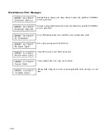
Page 146: ...A checksum error occured during MIDI data reception Attempt to transmit bulk out or receive bulk data while device number is set to off Bulk data was received but ignored because bulk protect function is on Bulk data reception was cancelled before completion The upper row of asterisksisthepreviousdisplay Anykeyoperationcancelsthisdisplay Memory Card Error Messages Attempt to save or load while mem...

Page 147: ...ta are erased This display will appear if you attempt to edit or perform a bulk dump of a track that contains no data a An external device has sent bulk data to the SY55 while the sequencer is running Bulk data cannot be received during sequencer operation so any received data will be ignored b You have attempted to operate a utility function while the sequencer is running The sequencer must be st...

Page 148: ...oltage malfunction Have the unit checked by qualified YAMAHA service personnel VoiceWith mismatched wave card ID exists in multi play setup Wave card not inserted in WAVE slot Voice ID and wave card ID do not match Voice number and voice type do not match Wrong bulk dump byte count or unrecognizeable bulk memory or card data 146 ...

Page 149: ... 000 notes max Display 16 character x 2 line backlit LCD Controls DATA ENTRY MASTER VOLUME PITCH MODULATION CLICK VOLUME Sequencer Keys Switches POWER INTERNAL CARD PRESET VOICE MULTI SEQ EDIT COMPARE UTILITY STORE COPY 1 NO 1 YES PAGE PAGE EXIT SELECT ENTER JOB RECORD STOP RUN numeric 0 9 Output Connectors PHONES OUTPUT L MONO R BREATH CONTROLLER SUSTAIN FOOT VOLUME MIDI Connectors IN OUT THRU Po...

Page 150: ...tune 60 12 18 94 102 93 18 Demo Drum set Voice Copy Function in Edit Mode Initialized Wave Assignments Preset Wave Assignments Edit Compare Key Operation Copy Function 5 54 55 Effect Copy Function List 56 95 107 85 Effect Balance Drum set Voice Voice 99 63 111 Effect Output Level Drum set Voice Multi play Voice 100 112 85 133 86 Effect On Off Effect Parameters Effect Type Drum set Voice Multi play...

Page 151: ...5 135 4 5 Bulk In Protect Bulk Out Device Number IN THRU and OUT Connectors Keyboard Transmit Channel Local Control Program Change Receive Channel Modulation Wheel Multi Key Multi Play 20 20 Mode Bank and Setup Selection Polyphony and Dynamic Note Allocation 101 113 89 97 109 59 61 60 Name Drum set Voice Multi play Voice Note Shift Drum set Voice Multi play Voice Note Limit High Low Oscillator 63 ...

Page 152: ... Event Song Clear Song Name 126 128 127 127 119 119 Song Program Sync Select Track Transmit Channel Split Keyboard Store Copy Key Store Functions 36 5 Multi play Setup Voice 25 46 28 118 132 3 Time Signature Transpose Tutorial Section How to Use Tune 97 109 Drum set Voice Multi play Utility Key 5 133 62 61 Velocity Curve Velocity Limit High Low Voice Architecture Edit Mode Function Selection Key M...

Page 153: ...Digital Musical Instrument products are frequently incorporated into Systems which are assembled on carts stands or in racks Utilize only those carts stands or racks that have been designed for this purpose and observe all safety pre cautions supplied with the products Pay special attention to cautions that relate to proper assembly heavier units being mounted at the lower levels load limits movin...

Page 154: ...lating to how a function or effect works when the unit is operating as designed arc not covered by the manufacturer s warranty Please study this manual carefully before requesting service NAME PLATE LOCATION The graphic below indicates the location of the Name Plate on your YAMAHA Digital Musical In strument The Model Serial Number Power requirements etc arc indicated on this plate You should note...

Page 155: ...SERVICE This product is supported by YAMAHA s worldwide network of factory trained and qualified dealer service personnel In the event of a problem contact your nearest YAMAHA dealer ...

Page 156: ...YAMAHA ...

Page 157: ...CO Lead Spirit VCF OZ Lead Get Lucky Gamma Band Metal Reed Modomatic DataStream Mystichoir St Michael Scatter Triton Amazon SatinGlass BrassChime Piano Mist Xanadu WdBass Duo Drum Set 1 Drum Set 2 No EL Name No Name No Name No 1 2 3 4 5 6 7 8 9 10 11 12 13 14 15 16 17 18 19 20 Piano E Piano1 E Piano2 E Piano3 E Piano4 E Piano5 E Piano6 E Piano7 Harpsi Organ 1 Organ 2 Pipe Trumpet Mute Tp Trombone ...

Page 158: ...L 7 NoteLimit H 8 Vel Limit L 9 Vel Limit H 10 Pan 1 1 EF Balance 24 FL R Scale 39 EF Others 40 VOICE Name 41 VOICE Edit Recall 42 VOICE Initialize Shaded blocks represent parameters available within a single job display 28 Element Initialize 29 CNTL Pitch Bend 30 CNTL AT P Bias 31 CNTL RandomPitch ...

Page 159: ...SEQUENCER REFERENCE BASIC RECORDING PROCEDURE FLOW ...

Page 160: ...G CLEAR YAMAHA YAMAHA CORPORATION P O Box1 Hamamatsu Japan Printed in Japan 3 DELETE Sourcetrack1 Source track 2 Destination track mixdown result One measure of 8th notes before quantization After quantization DeleteM004 006 Measure 4 through 6 deleted Subsequentmeasures moved back Measures 4 6 blank contain only rests TRACK 1 Erase TR1 M004 006 TRACK 1 TRACK 2 Result with new measure numbers Copy...

Page 161: ...YAMAHA MUSIC SYNTHESIZER MIDI DATA FORMAT ...

Page 162: ...er F0H 43H 1nH 35H 0FH System F0H 43H 1nH 35H 7FH Error Information F0H 43H 1nH 04H 40H Master Tuning Bulk Dump F7H F7H F7H F7H F7H F7H F7H F7H F7H F7H F7H F0H 43H 0nH 7AH bbH bbH LM_8103VC Voice Data F0H 43H 0nH 7AH bbH bbH LM_8103MU Multi Data F0H 43H 0nH 7AH bbH bbH LM_8103SY System Data sum F7H sum F7H sum F7H ACTIVE SENSING FEH SW1 SW2 SW3 SW4 SW5 1 MIDI OUT SW1 SW5 SW2 SW3 SW4 MIDI Transmit ...

Page 163: ...03MU LM_8103SY Bulk Dump 7AH 7AH 2nH 2nH 2nH 43H 43H 43H F0H F0H F0H F0H F0H F0H 43H 43H 43H 0nH 0nH 0nH 7AH 7AH 7AH bbH bbH bbH bbH bbH bbH LM_8103VC LM_8103MU LM_8103SY Voice Data Multi Data System Data Switch Remote F0H 43H 1nH 35H 0DH Switch Remote Test F7H sum F7H sum F7H sum F7H F7H F7H F7H F7H F7H F7H F7H F7H F7H F7H F7H F7H F7H 8nH 9nH BnH 00H 3FH BnH 41H 78H BnH 40H CnH DnH EnH F7H FEH MI...

Page 164: ...bers received 3 1 3 CONTROL CHANGE STATUS CONTROL NUMBER CONTROL VALUE 1011nnnnB 0cccccccB 0vvvvvvvB BnH n VOICE CHANNEL NUMBER The transmitted control number c 1 c 2 c 6 c 7 c 64 MODULATION WHEEL BREATH CONTROLLER DATA ENTRY SLIDER AT PLAY MODE FOOT VOLUME SUSTAIN SWITCH v 0 127 v 0 127 v 0 127 v 0 127 v 0 OFF 127 ON The received control number c 0 120 These control numbers can be assigned to the...

Page 165: ... PLAY MODE INTERNAL CARD PRESET INTERNAL CARD PRESET Transmitted in the play mode only Reception transmission ON OFF normal mode or direct mode can be selected Sequencer receives and transmits in direct mode at all times NORMAL MODE Select voice or multi number only Mode or memory cannot be selected Transmit VOICE PLAY MODE Voice number transmitted if voice number changed p 0 63 MULTI PLAY MODE Mu...

Page 166: ...120 Internal voice selected if preset multi currently active Voice with same memory number as multi selected if internal or card multi currently active d 122 124 p 0 63 VOICE or d 125 127 p 64 79 MULTI changes mode memory voice or multi number 3 1 5 CHANNEL PRESSURE AFTERTOUCH STATUS PRESSURE VALUE 1101nnnnB 0vvvvvvvB DnH n VOICE CHANNEL NUMBER v 0 127 Aftertouch can be assigned to the following f...

Page 167: ...te switch 3 3 1 PARAMETER CHANGE STATUS IDENTIFICATION SUB STATUS GROUP NUMBER STRUCTURE NUMBER MSB STRUCTURE NUMBER LSB PARAMETER NUMBER MSB PARAMETER NUMBER LSB PARAMETER VALUE MSB PARAMETER VALUE LSB EOX 11110000B 01000011B 0001nnnnB 00110101B 0000ttttB 0feennnnB 0pppppppB 0pppppppB 0vvvvvvvB 0vvvvvvvB 11110111B F0H 43H 1nH 35H F7H The 10 parameter change messages from MULTI COMMON to SYSTEM sh...

Page 168: ...t 1 chart 1 chart 2 chart 2 chart 3 chart 4 chart 5 chart 6 chart 7 chart 8 chart 9 note element number 0 EL1 3 EL4 channel number 0 CH1 15 CH16 filter number 0 filter 1 filter 2 don t care filter common key note number 36 C1 96 C6 Unused bits of the structure number LSB are transmitted as 0 s and ignored when received The unused bit of the parameter number MSB are transmitted as 0 s and ignored w...

Page 169: ...EMORY NUMBER DATA CHECK SUM EOX 2 s complement of 7 bits sum of all data bytes F7H The 3 types of bulk data shown in the chart below are transmitted and received Device number receive transmit on off and receive protect can be set in the utility mode Received to edit buffer regardless of protect setting Type b m x y VOICE MULTI SYSTEM 1AWM 2AWM 4AWM DRUM SET 01H 02H 04H 04H 38H 31H 23H 64H 01H 3AH...

Page 170: ... 20H ASCII _ DATA FORMAT 00111000B 38H ASCII 8 NAME 00110001B 31H ASCII 1 00110000B 30H ASCII 0 00110011B 33H ASCII 3 0mmmmmmmB ASCII 0mmmmmmmB ASCII ADDITIONAL 0000000B 00H HEADER 0000000B 00H 0000000B 00H 0000000B 00H 0000000B 00H 0000000B 00H 0000000B 00H 0000000B 00H 0000000B 00H 0000000B 00H 0000000B 00H 0000000B 00H 0000000B 00H 0000000B 00H MEMORY TYPE 0xxxxxxxB MEMORY NUMBER 0yyyyyyyB EOX ...

Page 171: ... keyboard are transmitted in the voice play mode whether the receive and transmit channel are matched or not Keyboard sequencer and MIDI note on messages are separated Keyboard sequencer and MIDI control data with the exception of sustain are not separated Sustain is separated 10 ...

Page 172: ... when the TG55 receives a bulk dump from the SY55 output select becomes stereo L R No n2 function 0 1 2 3 4 5 6 7 8 9 00 01 02 03 04 05 06 07 08 09 Multi Voice Set Name value v2 20 127 v2 20 127 v2 20 127 v2 20 127 v2 20 127 v2 20 127 v2 20 127 v2 20 127 v2 20 127 v2 20 127 note 0 multi 1 16 1 16ch v2 0 16 Effect Source Select 0A 10 No n2 function value note 0 00 Voice on off Output Select only TG...

Page 173: ... F7H note n device number n2 parameter number v2 parameter value note Element select mode 5 7 can be selected for voice number 1 62 The element select mode is fixed at 10 for voice number 63 and 64 2 Voice Common MIDI Parameter Change Format F0H 43H 1nH 35H 02H 00H 00H n2H 00H v2H F7H note n device number n2 parameter number v2 parameter value 12 No n2 function value note 5 1AWM_poly 6 2AWM_poly 7...

Page 174: ... Reserve EG Bias Device assign MIDI control Bias Range Voice Volume Device assign MIDI control Volume Limit Low Random Pitch Fluctuation Output Select only TG55 Voice Volume AWM_card ID MSB AWM_card ID LSB 6 7 16 17 8 9 18 19 10 11 12 13 14 15 16 17 18 19 20 1C ID 1E IF 20 21 22 23 24 note Only numbers with an asterisk apply to drum set voices The SY55 transmits bulk dump when output select 0 Thus...

Page 175: ...o n2 function value note 0 1 2 3 4 5 6 7 00 01 02 03 04 05 06 Alternate Group Wave on off Output Select only TG55 Wave Source Wave Number Wave Volume Wave Tuning Wave Note Shift Static Pan v2 b6 0 1 b5 0 1 b0 1 2 0 4 v2 v1 v2 v2 v2 v2 v2 0 127 0 127 16 100 1 63 0 1 0 127 0 1 0 off 1 on 0 off 1 on 0 str 1 off 2 1 3 2 4 12 0 pre 1 card 0 max 255 0 127 64 63 16 100 48 36 1 63 31 31 No effect when Mul...

Page 176: ... 0 255 3 4 5 6 02 03 04 05 Frequency Mode Fixed Mode Note Frequency Fine Pitch Modulation Sensitivity v2 v2 v2 v2 0 1 0 127 0 127 0 7 0 normal 1 fixed 0 127 64 63 Pitch EG 7 8 9 10 11 12 13 14 15 16 17 18 06 07 08 09 0A 0B 0C 0D 0E 0F 10 11 Key_on Rate 1 Key_on Rate 2 Key_on Rate 3 Key_off Rate 1 Key_on Level 0 Key_on Level 1 Key_on Level 2 Key_on Level 3 Key_off Level 1 Range Rate Scaling Velocit...

Page 177: ...ing Break Point 1 Out level Scaling Break Point 2 Out level Scaling Break Point 3 Out_level Scaling Break Point 4 v2 v2 v2 v2 v2 v2 v2 v2 v2 v2 v2 v2 v2 0 1 0 63 0 63 0 63 0 63 0 63 0 63 0 63 0 15 0 127 0 127 0 127 0 127 13 14 15 16 17 18 19 20 21 22 23 5C 5D 5E 5F 60 61 62 Out_level Scaling Offset 1 Out level Scaling Offset 2 Out_level Scaling Offset 3 Out_level Scaling Offset 4 Velocity Sensitiv...

Page 178: ...Scaling Break Point 2 C off lvl Scaling Break Point 3 C_off_lvl Scaling Break Point 4 v2 v2 v2 v2 v2 v2 v2 v2 v2 v2 v2 v2 v2 v2 v2 v2 v2 v2 v2 v2 v2 0 2 0 127 0 2 0 63 0 63 0 63 0 63 0 63 0 63 0 127 0 127 0 127 0 127 0 127 0 127 0 127 0 15 0 127 0 127 0 127 0 127 0 THR 1 LPF 2 HPF 2 HPF in Filter 1 only 0 EG 1 LFO 2 EGVA 0 127 64 63 0 127 64 63 0 127 64 63 0 127 64 63 0 127 64 63 0 127 64 63 0 127...

Page 179: ...range off 00H 3FH on 40H 7FH n2 switch SY55 00 01 02 03 04 05 07 08 09 0A OB 0C 0E OF 10 11 12 13 15 16 17 18 19 1A 1C 1D 1E 1F 20 21 23 24 25 26 27 28 7F PRESET RUN VOICE EDIT COMPARE JOB SELECT EXIT ENTER 3 6 9 CARD STOP MULTI UTILITY PAGE 1 YES 2 5 8 INTERNAL TOP REC SEQ STORE COPY PAGE 1 NO 0 1 4 7 Initial Set o o o o o o o o o o o o o o o o o o o o o o o o o o o o o o o o o o o o o ...

Page 180: ...uning Master Note Shift Master Fine Tuning Velocity Velocity Curve Select MIDI Keyboard Transmit Channel Receive Channel Local Switch Device Number Bulk Data Memory Protect Switch Program Change Mode v2 DT 0 127 0 127 v2 0 7 v2 v2 v2 v2 v2 v2 0 15 0 16 0 1 0 17 0 1 0 2 0 127 64 63 0 127 64 63 0 4 1 8 0 15 1 16ch 0 15 1 16ch 16 omni 0 off 1 on 0 off 1 16 1 16 17 all 0 off 1 on 0 off 1 normal 2 dire...

Page 181: ...uffer Full SEQ Buffer Full MIDI Data MIDI Check Sum MIDI Device off MIDI Bulk Prot No Data Card Data Card Prot Data Card Format Illegal Data Verify Failed Internal Bat Lo Data Card Bat Lo SEQ Memory Full SEQ Data Empty NowSEQRunning Song Data Exist Internal Bat NG Data Card Bat NG ID Mismatch No Wave Card Wrong Wave Card Now SEQ Running not defined Voice Type Song Cleared not error 1E 1F 20 Bulk R...

Page 182: ...10111B F7H 2 2AWM STATUS 11110000B F0H IDENTIFICATION 01000011B 43H SUB STATUS 0000nnnnB 0nH n DEVICE NUMBER FORMAT NUMBER 01111010B 7AH BYTE COUNT MSB 00000010B 02H BYTE COUNT LSB 00110001B 31H Byte Count 305 HEADER 26 byte see 3 3 2 BULK DUMP VOICE HEADER 11 byte see chart 2 EFFECT 5 byte see chart 5 VOICE COMMON 21 byte see chart 2 ELEMENT 0 DATA 9 byte see chart 2 ELEMENT 1 DATA 9 byte see cha...

Page 183: ...ee chart 6 FILTER 2 29 byte see chart 6 FILTER COMMON 3 byte see chart 6 AWM ELEMENT DATA 2 24 byte see chart 4 ELEMENT 1 AWM ELEMENT DATA 1 27 byte see chart 4 FILTER 1 29 byte see chart 6 FILTER 2 29 byte see chart 6 FILTER COMMON 3 byte see chart 6 AWM ELEMENT DATA 2 24 byte see chart 4 ELEMENT 2 AWM ELEMENT DATA 1 27 byte see chart 4 FILTER 1 29 byte see chart 6 FILTER 2 29 byte see chart 6 FI...

Page 184: ...S 11110000B F0H IDENTIFICATION 01000011B 43H SUB STATUS 0000nnnnB 0nH n DEVICE NUMBER FORMAT NUMBER 01111010B 7AH BYTE COUNT MSB 00000001B 01H BYTE COUNT LSB 00111010B 3AH Byte Count 186 HEADER 26 byte see 3 3 2 BULK DUMP MULTI HEADER 11 byte see chart 1 EFFECT 5 byte see chart 5 CH_0 VOICE 9 byte see chart 1 CH15 VOICE 9 byte see chart 1 CHECK SUM 0eeeeeeeB 2 s complement of 7 bits sum of all dat...

Page 185: ...H bbH bbH 24H 32H bbH bbH SEQ Setup Parameter Change LM_8103SS Setup Data sum LM_8103SQ Song Data sum LM_NSEQ_ NSEQ Data sum LM_8103SA All Data sum F7H F7H F7H F7H F7H SW1 SW2 SW3 SW4 MIDI Transmit Channel Transmit channel selection for each track Program Change Mode Select Program change transmission ON OFF normal mode or direct mode can be selected MIDI Control Transmit ON OFF can be selected Sy...

Page 186: ...3SA All Data sum F7H F7H F7H F7H F7H F7H SW1 SW2 SW3 SW4 SW5 SW6 SW7 MIDI Receive Channel Record receive channel can be selected Velocity Filter Velocity recording ON OFF can be selected Aftertouch Filter Aftertouch recording ON OFF can be selected Clock Condition Select Internal timing clock or external timing clock received via MIDI IN can be selected MIDI Control Receive ON OFF can be selected ...

Page 187: ...CnH n VOICE CHANNEL NUMBER p 0 118 DIRECT MODE STATUS MODE MEMORY NUMBER PROGRAM NUMBER 1100nnnnB 0dddddddB 0pppppppB CnH n VOICE CHANNEL NUMBER d 119 127 p 0 79 MODE MEMORY NUMBER d 119 d 120 d 121 d 122 d 123 d 124 d 125 d 126 d 127 INDIVIDUAL INTERNAL INDIVIDUAL CARD INTERNAL and CARD cannot be combined in one MULTI INDIVIDUAL PRESET COMMON VOICE PLAY MODE INTERNAL COMMON VOICE PLAY MODE CARD C...

Page 188: ...iming clock received via MIDI IN can be selected Transmit ON OFF can be selected STATUS 11111010B FAH Transmit receive ON OFF can be selected STATUS 11111011B FBH Transmit receive ON OFF can be selected STATUS 11111100B FCH Transmit receive ON OFF can be selected Exclusive messages not received in demo mode STATUS IDENTIFICATION SUB STATUS GROUP NUMBER STRUCTURE NUMBER MSB STRUCTURE NUMBER LSB PAR...

Page 189: ...00111000B 00110001B 00110000B 00110011B 0mmmmmmmB 0mmmmmmrnB 00000000B 00000000B 00000000B 00000000B 00000000B 00000000B 00000000B 00000000B 00000000B 00000000B 00000000B 00000000B 00000000B 0xxxxxxxB 0yyyyyyyB 0dddddddB F0H 43H 0nH 7AH 4CH 4DH 20H 20H 38H 31H 30H 33H 00H 00H 00H 00H 00H 00H 00000000B 00H 00H 00H 00H 00H 00H 00H 00H n DEVICE NUMBER ASCII L ASCII M ASCII _ ASCII _ ASCII 8 ASCII 1 A...

Page 190: ... protect can be selected in UTILITY mode Reception possible only in modes other than play and record LM_NSEQ1_ bulk header can also be received however macro odd time signatures and exclusive data will be ignored When song data or NSEQ data is received the data is loaded into that song only when that song is empty When all data is received the received data is loaded and all previous data is erase...

Page 191: ...iple bulk dumps are received Not receive MIDI Parameter Change Format F0H 43H 1nH 35H 0EH 00H 00H n2H 00H v2H F7H note n device number n2 parameter number v2 parameter value No function value note 0 1 2 3 4 5 6 7 8 9 Click Condition Clock Condition Rec Channel After Touch Record SW Velocity Record SW Song Number Rec Type MIDI Control Reserve Reserve 0 3 0 1 0 17 0 1 0 1 0 7 0 3 0 1 0 0 0 off 1 rec...

Page 192: ...e event control data end of record track 2 7 data top of track 8 time event control data end of record Add NSEQ time event control data DATA FORMAT binary short time long time short note long note short note long note measure mark no operation 0ttttttt 0ttttttt 0ttttttt 10dddddd 0kkkkkkk 0vvvvvv 11dddddd 0ddddddd 0kkkkkkk 0vvvvvvv 10dddddd 1kkkkkkk 110ddddd 0ddddddd 1kkkkkkk ddd duration kkk MIDI ...

Page 193: ...32 ...

Page 194: ...anged Default Mode Messages Altered Note Number True voice Velocity Note ON Note OFF After Key s Touch Ch s Pitch Bender 0 1 2 Control 3 5 6 Change 7 8 63 64 65 120 x o o x o play mode o x o x o o 0 12 semi 7 bit resolution o o o o o o o o o Modulation Wheel Breath Control Data Entry Knob Volume Sustain Switch Prog Change True o 0 79 119 127 o 0 79 119 127 0 6 3 if program on System Exclusive o o ...

Page 195: ...Note OFF o 9nH v 1 127 x 9nH v 0 After Key s Touch C h s o o o o Pitch Bender 0 120 Control Change Prog Change True o 0 127 o 0 127 System Exclusive o o System Song Pos Song Sel Common Tune x x x System Clock Real Time Commands o MIDI cont on o MIDI cont on Aux Local ON OFF All Notes OFF Mes Active Sense sages Reset x x x x x x x x Notes 1 receive if velocity record switch is on if switch is off v...

Page 196: ...YAMAHA YAMAHA CORPORATION P O Box1 Hamamatsu Japan Printed in Japan ...

Page 197: ...YAMAHA Yamaha Corporation of America 6600 Orangethorpe Avenue P O Box 6600 Buena Park CA 90622 6600 SY55 OM 7 22 98 29313 ...

Reviews: