VOICE EDIT MODE
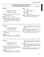
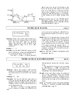
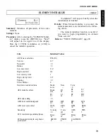
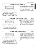
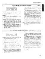
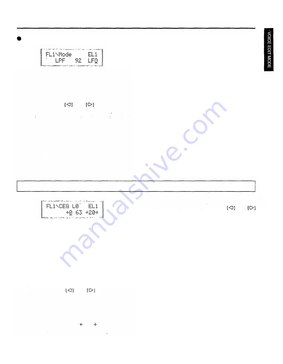
Summary: Determines whether the cutoff frequency
of the selected filter will be controlled by the
LFO or by the filter envelope generator (EG).
Settings: EG, LFO, EGVA
Mode
Procedure: Use the
and
select the Mode parameter. Use the [DATA EN-
TRY] control or [+1/YES] and [-1/NO] keys to
select the "EG" or "LFO" setting.
Filter 1 or Filter 2 can be selected by holding
the [SELECT] key and pressing the numeric [9]
or [6] key, respectively.
Details: Varying the filter cutoff frequency can
ceate "sweep" or "wah-wah" type effects. If the
cutoff is controlled via the LFO a cyclic vari-
ation based on the "shape" of the selected LFO
cursor keys to
waveform is produced. If EG control is selected,
the filter envelope generator (a separate EG is
provided for each filter — see "FILTER: CUT-
OFF ENVELOPE GENERATOR" below) can be
set up to produce a wide range of time-based
variations.
Please note that if "LFO" is selected, the
filter cutoff envelope generator parameters have
no effect on the sound and will not appear on the
display: Cutoff EG levels and rates, rate scaling,
and level scaling. The filter can only be con-
trolled from controllers (modulation wheel, etc.)
if the LFO mode is selected.
If the "EGVA" setting is selected, the R1
and L1 envelope parameters arc controlled by
note velocity (i.e. the harder a key is played the
higher the Rl speed and L1 level). All EG para-
meters are controlled by note velocity when
"EG" is selected.
Refer to: Tutorial, page 37, 45. "FILTER: CUTOFF
ENVELOPE GENERATOR," below.
FILTER: CUTOFF ENVELOPE GENERATOR
JOB 23
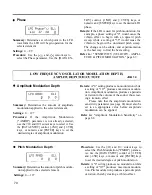
Summary: All parameters within this function de-
termine the "shape" of the cutoff envelope gen-
erator for the selected filler. This function is
only available if the "Mode" parameter (page
63) is set to "EG" or "EGVA."
Settings:
L0, L1, L2, L3, L4, RL1 and RL2 parameters:
-64 ... +63
R1, R2, R3, R4, RR1 and RR2 parameters:
0 ... 63
meters can be accessed by moving the cursor in
Procedure: Use the
and
cursor keys to
select the various rate and level parameters in
turn (L0, R1, L1, R2, L2, R3, L3, R4, L4, RR1,
RL1, RR and RL2), using the [DATA ENTRY]
control, [-1/NO] and [+1/YES] keys, or numeric
and [ENTER] keys to set the value of each.
The arrow symbols (
and
) that appear at
either end of the display mean that more para-
the indicated direction using the
and
keys.
The filter 1 or filter 2 envelope generator
can be selected by holding the [SELECT] key
and pressing the numeric [9] or [6] key, respec-
tively.
Details: The cutoff envelope generator level para-
meters correspond to cutoff frequency. Plus "+"
values produce higher cutoff frequencies while
minus "-" values produce lower cutoff frequen-
cies. "0" level values produce the normal cutoff
frequency as determeined by the cutoff parame-
ter (See "Cutoff" on page 74).
The "Rate" parameters work in the same way
as the amplitude, and pilch envelope generator
rate parameters: a selling of "0" produces the
slowest rate between levels, while the maximum
setting of "63" produces the fastest (almost in-
stantaneous) change.
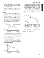
The pilch envelope begins at L0 (Level 0),
moves to L1 (Level 1) at a rate determined by
the selling of R1, then to L2 (Level 2) at R2
75
Summary of Contents for SY55
Page 1: ...YAMAHA AUTHORIZED PRODUCT MANUAL MUSIC SYNTHESIZER ...
Page 2: ...YAMAHA MUSIC SYNTHESIZER ...
Page 4: ...SY55 Music Synthesizer Operating Manual ...
Page 12: ...TUTORIALS SECTION ...
Page 42: ...TUTORIALS SY55 Voice Parameter Chart Voice Name 39 ...
Page 43: ...SY55 Voice Parameter Chart Voice Name VeloChorus 40 ...
Page 51: ...REFERENCE SECTION ...
Page 59: ...VOICE EDIT MODE 57 ...
Page 105: ...DRUM EDIT MODE 103 ...
Page 117: ...MULTI EDIT MODE 115 ...
Page 131: ...SEQUENCER MODE 129 ...
Page 145: ...UTILITY MODE 143 ...
Page 156: ...YAMAHA ...
Page 159: ...SEQUENCER REFERENCE BASIC RECORDING PROCEDURE FLOW ...
Page 161: ...YAMAHA MUSIC SYNTHESIZER MIDI DATA FORMAT ...
Page 193: ...32 ...
Page 196: ...YAMAHA YAMAHA CORPORATION P O Box1 Hamamatsu Japan Printed in Japan ...


