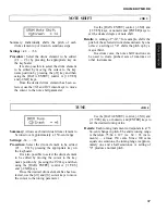
CONTROLLER: AMPLITUDE MODULATION
JOB 32
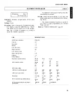
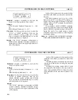
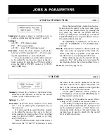
Summary: Assigns a controller to, and sets the
maximum depth of amplitude modulation ap-
plied by the LFO.
Settings:
CTL# (Control Number) Parameter: 0 ... 120,
AT
RNG (Range) Parameter: 0 ... 127
Procedure: Use the
and
"CTL#" or "RNG" parameter, then use the
[DATA ENTRY] control, [-1/NO] and [+1/YES]
keys, or numeric and [ENTER] keys to set the
selected parameter as required.
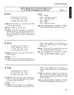
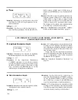
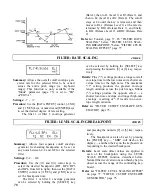
Details: The "CTL#" parameter corresponds to
MIDI control numbers. Standard controller as-
signments are noted in the upper right-hand cor-
ner of the display:
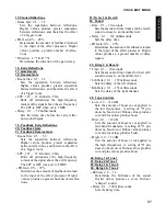
Set the CTL# parameter to the number of the
controller with which you intend to control this
function.
The RNG parameter can be set to a value be-
tween 0 and 127. A setting of "0" produces no
change when the assigned controller is operated,
while a setting of "127" produces the maximum
possible change.
If you assign a breath controller (CTL# 2) to
amplitude modulation, for example, the harder
you blow into the breath controller, the greater
will be the depth of the amplitude modulation
produced. Please note that the amplitude modu-
lation sensitivity parameter described on page
?? must be set to an appropriate value before
amplitude modulation will function.
Refer to: "SENSITIVITY (VELOCITY, AMPLI-
TUDE & PITCH MODULATION)," page 67.
keys to select the
CONTROLLER: PITCH MODULATION
JOB 33
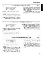
Summary: Assigns a controller to, and sets the
maximum depth of pitch modulation applied by
the LFO.
Settings:
CTL# (Control Number) Parameter: 0 ... 120,
AT
RNG (Range) Parameter: 0 ... 127
Procedure: Use the
and
"CTL#" or "RNG" parameter, then use the
[DATA ENTRY] control, [-1/NO] and [+1/YES]
keys, or numeric and [ENTER] keys to set the
selected parameter as required.
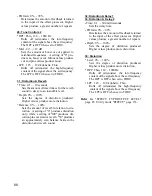
Set the CTL# parameter to the number of the
controller with which you intend to control this
function.
The RNG parameter can be set to a value be-
tween 0 and 127. A setting of "0" produces no
change when the assigned controller is operated,
while a setting of "127" produces the maximum
possible change.
If you assign the modulation wheel (CTL# 1) to
pitch modulation, for example, rolling the modu-
lation wheel away from you will produce deeper
pitch modulation. Please note that the pitch
modulation sensitivity parameter described on
page ?? must be set to an appropriate value be-
fore pitch modulation will function.
Refer to: "SENSITIVITY (VELOCITY, AMPLI-
TUDE & PITCH MODULATION)," page 67.
keys to select the
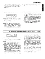
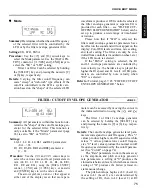
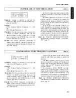
Details: The "CTL#" parameter corresponds to
MIDI control numbers. Standard controller as-
signments are noted in abbreviations shown in
the upper right-hand comer of the display:
82
Summary of Contents for SY55
Page 1: ...YAMAHA AUTHORIZED PRODUCT MANUAL MUSIC SYNTHESIZER ...
Page 2: ...YAMAHA MUSIC SYNTHESIZER ...
Page 4: ...SY55 Music Synthesizer Operating Manual ...
Page 12: ...TUTORIALS SECTION ...
Page 42: ...TUTORIALS SY55 Voice Parameter Chart Voice Name 39 ...
Page 43: ...SY55 Voice Parameter Chart Voice Name VeloChorus 40 ...
Page 51: ...REFERENCE SECTION ...
Page 59: ...VOICE EDIT MODE 57 ...
Page 105: ...DRUM EDIT MODE 103 ...
Page 117: ...MULTI EDIT MODE 115 ...
Page 131: ...SEQUENCER MODE 129 ...
Page 145: ...UTILITY MODE 143 ...
Page 156: ...YAMAHA ...
Page 159: ...SEQUENCER REFERENCE BASIC RECORDING PROCEDURE FLOW ...
Page 161: ...YAMAHA MUSIC SYNTHESIZER MIDI DATA FORMAT ...
Page 193: ...32 ...
Page 196: ...YAMAHA YAMAHA CORPORATION P O Box1 Hamamatsu Japan Printed in Japan ...


