VOICE EDIT MODE
Please note that the pitch modulation sensi-
tivity parameter (see page 68) must also be set
to an appropriate value before pitch modulation
can be applied.
Refer to: "Pitch Modulation Sensitivity" on page
68.
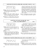
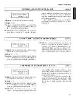
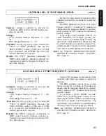
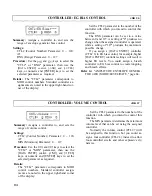
Filter Cutoff Modulation Depth
Summary: Determines the amount of modulation
applied to the cutoff frequency of the filter of
the selected element.
Settings: 0 ... 127
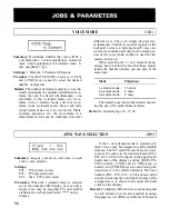
Procedure: Use the and cursor keys to
Details: A "0" setting produces no modulation while
a setting of "127" produces maximum modula-
tion. Filter cutoff modulation produces wah-wah
type effects.
Please note that the filter cutoff modulation
sensitivity parameter (see page 78) must also be
set to an appropriate value before cutoff fre-
quency modulation can be applied.
Refer to: Tutorial, page 37. "FILTER: RESO-
NANCE/VELOCITY SENSITIVITY/MODU-
LATION SENSITIVITY" on page 77.
select the Filter Cutoff Modulation ("Cut-
ofMOD") parameter. Use the [DATA ENTRY]
control, [-1/NO] and [+1/YES] keys, or numeric
and [ENTER] keys to set the desired degree of
cutoff modulation.
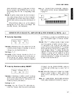
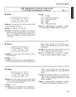
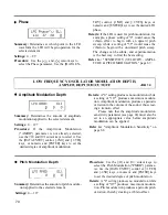
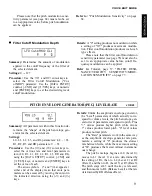
PITCH ENVELOPE GENERATOR (PEG) LEVEL/RATE
JOB 20
Summary: All parameters within this function de-
termine the "shape" of the pitch envelope gen-
erator for the selected element.
Settings:
L0, L1, L2, L3, and RL parameters: -64 ... +63
R1, R2, R3 and RR parameters: 0 ... 63
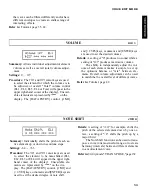
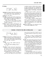
Procedure: Use the and cursor keys to
select the various rate and level parameters in
turn (L0, Rl, L1, R2, L2, R3, L3, RR and RL),
using the [DATA ENTRY] control, [-1/NO] and
[+1/YES] keys, or numeric and [ENTER] keys to
set the value of each.
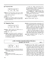
The arrow symbols ( and )that appear at
either end of the display mean that more para-
meters can be accessed by moving the cursor in
the indicated direction using the and
keys.
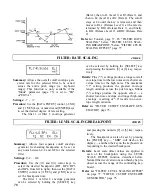
Details: Unlike the amplitude envelope generator,
the "Level" parameters of which actually corre-
spond to volume levels, the pitch envelope gen-
erator level parameters correspond to pitch. Plus
"+" values produce higher pitch while minus
"-" values produce lower pitch. "0" level values
produce normal pitch.
The "Rate" parameters work in the same way
as the amplitude envelope generator rate para-
meters: a setting of "0" produces the slowest
rate between levels, while the maximum setting
of "63" produces the fastest (almost instantane-
ous) change.
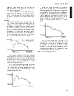
The pitch envelope begins at L0 (Level 0),
moves to L1 (Level 1) at a rate determined by
the setting of R1, then to L2 (Level 2) at R2
(Rate 2), and then to L3 (Level 3) at R3 (Rate 3).
The pitch stays at L3 until the key is released,
and then moves to RL (Release Level) at the rate
determined by RR (Release Rate).
71
Summary of Contents for SY55
Page 1: ...YAMAHA AUTHORIZED PRODUCT MANUAL MUSIC SYNTHESIZER ...
Page 2: ...YAMAHA MUSIC SYNTHESIZER ...
Page 4: ...SY55 Music Synthesizer Operating Manual ...
Page 12: ...TUTORIALS SECTION ...
Page 42: ...TUTORIALS SY55 Voice Parameter Chart Voice Name 39 ...
Page 43: ...SY55 Voice Parameter Chart Voice Name VeloChorus 40 ...
Page 51: ...REFERENCE SECTION ...
Page 59: ...VOICE EDIT MODE 57 ...
Page 105: ...DRUM EDIT MODE 103 ...
Page 117: ...MULTI EDIT MODE 115 ...
Page 131: ...SEQUENCER MODE 129 ...
Page 145: ...UTILITY MODE 143 ...
Page 156: ...YAMAHA ...
Page 159: ...SEQUENCER REFERENCE BASIC RECORDING PROCEDURE FLOW ...
Page 161: ...YAMAHA MUSIC SYNTHESIZER MIDI DATA FORMAT ...
Page 193: ...32 ...
Page 196: ...YAMAHA YAMAHA CORPORATION P O Box1 Hamamatsu Japan Printed in Japan ...


