4. Sample Dump
5.2 Channel message
For the sample dump the SYXS uses the Sample Dump Standard and SY99 Sample Bulk Dump.
Both of them can be received.
For transmission, the above two data types are is transmitted successively when Sample Dump of the
Sample Utility is executed. When receiving Sample Dump Standard Dump Request, and SY99 Sample
Bulk Dump Request, each data type is transmitted.
With Sample Dump Standard and SY99 Sample Bulk Dump $lf is the upper limit of the Sample (mem-
ory) Number and the number exceeding this is handled as $1f.
Sample Dump Standard
DUMP REQ F0,7E,cc,03.ss,ss,F7
ACK F0,7E,cc,7F,pp,F7
NAK F0,7E,cc,7E,pp,F7
CANCEL F0,7E,cc,7D,pp,F7
WAIT F0,7E,cc,7C,pp,F7
DATA PACKET F0,7E,cc,02,kk,<120 byte>,11,F7
DUMP HEADER F0,7E,cc,01,ss,ss,ee,ff,ff,ff,gg,gg,hh,hh,hh
,ii,ii,ii,jj,F7
Reception is carried out only during recording. Transmission is performed only when playing and over.
dubbing.
Refer to the Receiver flow chart and Transmit flow chart for the transmission and reception conditions.
5.3 Mode message
Transmission and reception are not carried out.
5.4 System common message
Only $F2 is received and the others are not transmitted or received.
5.5 System real time message
5.5.1
Status F8, FA, FB, FC
are received.
5.5.2 Nothing is carried out with Status F9, FD, and FF after being read.
pp
: packer number
c c
: channel number
ss ss : sample number (LSB first)
cc : sample format (SY99 handles 8-I6bits.)
ff ff ff : sample period (LSB first)
gg gg gg : sample length (LSB first)
hh hh hh : loop start (LSB first)
ii ii ii : loop end (LSB first)
j j
: loop type (00=normal Loop,01=alternate Loop.
7F=Loop off)
6. Status FE (active sensing)
a ) T r a n s m i s s i o n
FE in transmitted approximately every 170 msec.
b) Reception
If a signal is not output from MIDI for longer than approximately 300msec after receiving FE, the
MIDI reception buffer is cleared, and if key on remains it is turned off.
kk
II
: running packet count(0-127)(sequential packet No.)
: checksum(XOR of 7E cc 02 kk <l20 bytes>)
5. Sequencer mode
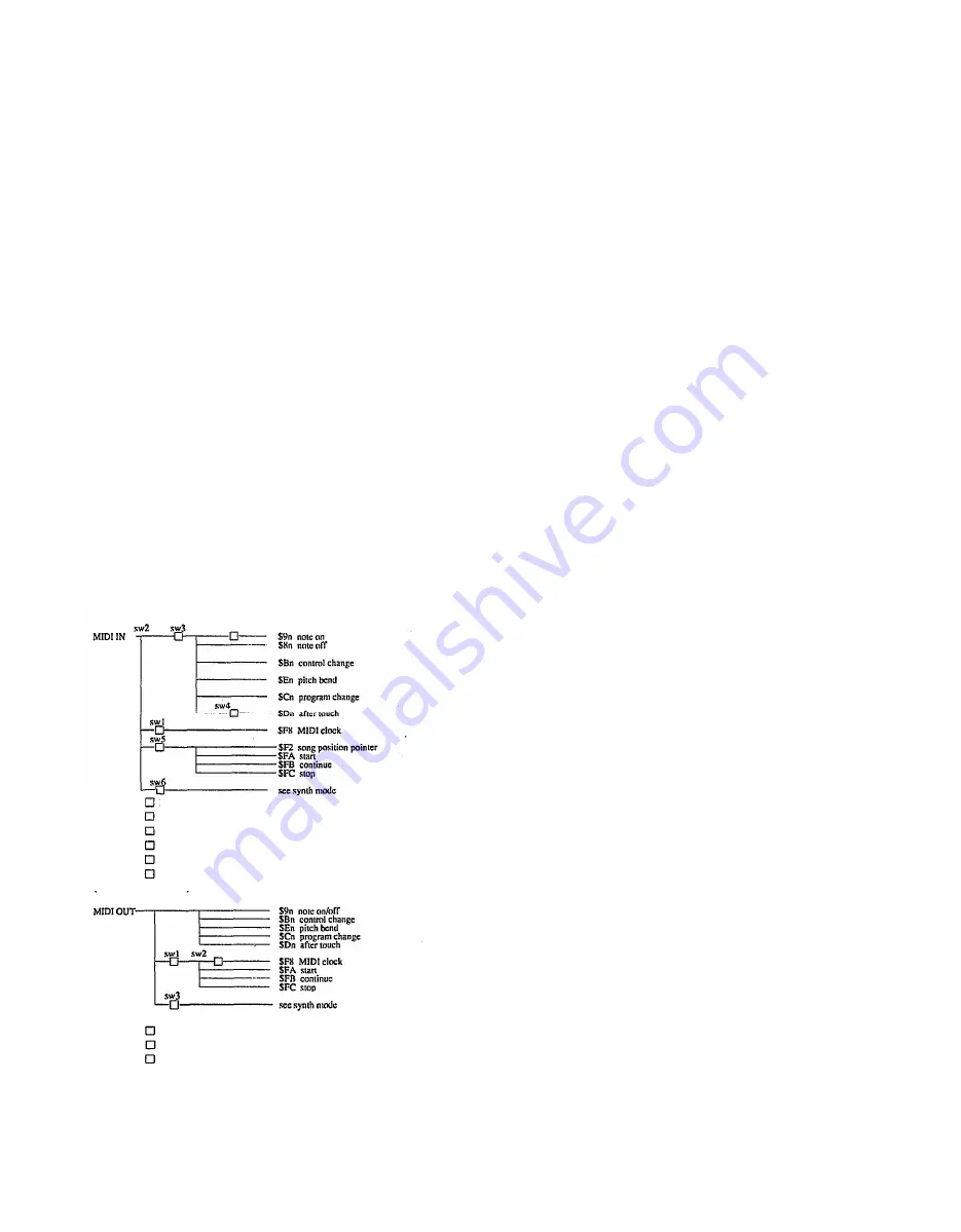
5.1 MIDI reception/transmission block diagram
(Receive flow chart)
(Note) sw1 It turns on when clock is set to MIDI in SEQ SETUP.
sw2 Receiving channel in SEQ SETUP during recording
sw3 Velocity setting 1~127, kbd in SEQ SETUP during recording
sw4 After touch on/off in SEQ SETUP during recording
sw5
MIDI control on/off in SEQ SETUP
sw6 Device Number setting in SETUP
(Note) sw1 MIDI control on/off in SEQ SETUP
sw2 It turns on when the clock is set to internal in SEQ SETUP
sw3 Device Number setting in SETUP
5
Summary of Contents for SY85
Page 1: ...YAMAHA YAMAHA AUTHORIZED PRODUCT MANUAL MUSIC SYNTHESIZER ...
Page 2: ...YAMAHA MUSIC SYNTHESIZER ...
Page 27: ...Internal Voice List INTERNAL VOICE 1 INTERNAL VOICE 2 24 2 Selecting And Playing Voices ...
Page 28: ...2 Selecting And Playing Voices 25 ...
Page 73: ...YAMAHA MUSIC SYNTHESIZER ...
Page 257: ...184 SONG EDIT MODE SONG JOB ...
Page 262: ...SONG EDIT MODE SONG JOB 189 ...
Page 334: ...EFFECT MODE parallel EFFECT 1 dual EFFECT 2 dual APPENDIX EFFECTS 263 ...
Page 360: ...INITIAL PERFORMANCE InitPerf APPENDIX INITIAL DATA BLANK CHART 289 ...
Page 361: ...INITIAL NORMAL VOICE InitVce 290 APPENDIX INITIAL DATA BLANK CHART ...
Page 362: ...APPENDIX INITIAL DATA BLANK CHART 291 ...
Page 363: ...INITIAL DRUM VOICE DR PTN 292 APPENDIX INITIAL DATA BLANK CHART ...
Page 364: ...APPENDIX INITIAL DATA BLANK CHART 293 ...
Page 365: ...INITIAL DRUM VOICE DR Zones 294 APPENDIX INITIAL DATA BLANK CHART ...
Page 366: ...APPENDIX INITIAL DATA BLANK CHART 295 ...
Page 367: ...INITIAL DRUM VOICE DR GMIDI 296 APPENDIX INITIAL DATA BLANK CHART ...
Page 368: ...APPENDIX INITIAL DATA BLANK CHART 297 ...
Page 369: ...INITIAL DRUM VOICE DR Efect 298 APPENDIX INITIAL DATA BLANK CHART ...
Page 370: ...APPENDIX INITIAL DATA BLANK CHART 299 ...
Page 371: ...INITIAL MULTI InitSong 300 APPENDIX INITIAL DATA BLANK CHART ...
Page 372: ...SYSTEM SETUP APPENDIX INITIAL DATA BLANK CHART 301 ...
Page 373: ...INITIAL PERFORMANCE LIST 1 302 APPENDIX INITIAL DATA BLANK CHART ...
Page 374: ...APPENDIX INITIAL DATA BLANK CHART 303 ...
Page 375: ...INITIAL PERFORMANCE LlST 2 304 APPENDIX INITIAL DATA BLANK CHART ...
Page 376: ...APPENDIX INITIAL DATA BLANK CHART 305 ...
Page 377: ...INITIAL VOICE LIST 1 306 APPENDIX INITIAL DATA BLANK CHART ...
Page 378: ...INITIAL VOICE LIST 2 APPENDIX INITIAL DATA BLANK CHART 307 ...
Page 379: ...INITIAL VOICE LIST 3 308 APPENDIX INITIAL DATA BLANK CHART ...
Page 380: ...INITIAL VOICE LIST 4 APPENDIX INITIAL DATA BLANK CHART 309 ...
Page 381: ...WAVE LIST 310 APPENDIX INITIAL DATA BLANK CHART ...
Page 382: ...BLANK CHART PERFORMANCE APPENDIX INITIAL DATA BLANK CHART 311 ...
Page 383: ...BLANK CHART VOICE 312 APPENDIX INITIAL DATA BLANK CHART ...
Page 384: ...APPENDIX INITIAL DATA BLANK CHART 313 ...
Page 385: ...BLANK CHART DRUM VOICE 314 APPENDIX INITIAL DATA BLANK CHART ...
Page 387: ...BLANK CHART MULTI 316 APPENDIX INITIAL DATA BLANK CHART ...
Page 388: ...BLANK CHART SYSTEM SETUP APPENDIX INITIAL DATA BLANK CHART 317 ...
Page 389: ...318 APPENDIX INITIAL DATA BLANK CHART ...
Page 394: ...APPENDIX ERROR MESSAGES 323 ...
Page 404: ...YAMAHA MUSIC SYNTHESIZER MIDI DATA FORMAT JCAGR0PT2 3CP Printed in Japan ...


