3-34
Outboard Rigging Guide - 2001
RECTIFIER 6HP~25HP
The rectifier allows the lighting coil to recharge
the battery as well as supply electrical current to
other accessories or components that might be on
board. Yamaha offers the rectifier as optional
equipment for the models listed below (it is stan-
dard on T9.9 models).
NOTE: For additional parts required for installa-
tion, see the list on the next page.
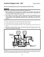
Rectifier
Installation Example (For F9.9)
1.
Remove the motor cover and locate the
mounting boss (empty bolt hole) on the star-
board side of the motor.
NOTE: The mounting boss is forward of the
number one spark plug and just to the rear of the
electrical wire connection cover.
2.
Mount the bracket onto the mounting boss by
the center hole in the bracket with a bolt and
washer.
NOTE: The bracket has a support key that
engages the stem of the mounting boss to ensure
proper bracket placement.
3.
Mount the rectifier onto the bracket using the
two other bolts and washers.
NOTE: Be sure the rectifier lead wires exit from
the bottom.
4.
Locate the electrical wire connection cover
and remove it.
5.
Dislodge the three green wire connectors
(originating from the lighting coil) from the
retainer (under the connection cover).
Connect the two primary green wires with the
green wire leads from the rectifier.
NOTE: The extra green wire connector from the
lighting coil will remain unused.
6.
Pass the red and black battery lead wires
through the slits in the rubber grommet at the
front of the motor pan.
Do not connect the battery lead wires to the
battery at this point.
7.
Connect the black eye-terminal lead wires
from the rectifier and battery to bolts on the
motor for grounding purposes.
8.
Connect one red lead wire from the fuse hold-
er assembly to either of the two red lead wires
from the rectifier.
NOTE: The other red lead wire from the rectifier
will remain unused.
9.
Connect the red lead wire from the battery to
the red lead wire from the other end of the
fuse holder assembly.
10. Insert all the wire connectors into the retainer
and reinstall the electrical connection cover.
NOTE: Be sure not to pinch any wires under-
neath the connection cover.
11. Install the fuse holder assembly into the hook
on top of the electrical connection cover.
Part Number
Applicable Model
6G8-81960-A1-00
F9.9
6G1-81970-00-00
6, 8, 9.9, 15, 25HP
WARNING
Summary of Contents for T8
Page 2: ......
Page 9: ......
Page 35: ......
Page 37: ......
Page 61: ......
Page 63: ......
Page 65: ...2 2 Outboard Rigging Guide 2001 Engine Mounting Dimensions...
Page 67: ...2 4 Outboard Rigging Guide 2001 Engine Mounting Dimensions...
Page 71: ...2 8 Outboard Rigging Guide 2001 Transom Mounting Patterns 25HP 2 Cylinder...
Page 72: ...2 9 Outboard Rigging Guide 2001 Transom Mounting Patterns 25X3 3 Cyl 30HP 40HP Manual Tilt...
Page 109: ......
Page 111: ......
Page 128: ...3 17 Outboard Rigging Guide 2001 Switch Panels Oil Lamp Panel Assembly T9 9ELR 6G8 83530 00 00...
Page 155: ...3 44 Outboard Rigging Guide 2001 Boat Wiring Diagrams T9 9 with 703 Control...
Page 156: ...3 45 Outboard Rigging Guide 2001 T9 9 with Switch Panel...
Page 177: ...3 66 Outboard Rigging Guide 2001 After Market Dash Wiring...
Page 178: ...3 67 Outboard Rigging Guide 2001 COMPLETE BOAT WIRING DIAGRAMS 70 90HP F80 F115...
Page 179: ...3 68 Outboard Rigging Guide 2001 Complete Boat Wiring Diagrams V4 V6 Single Engine...
Page 180: ...3 69 Outboard Rigging Guide 2001 Complete Boat Wiring Diagrams V4 V6 Single Engine Cont d...
Page 181: ...3 70 Outboard Rigging Guide 2001 Complete Boat Wiring Diagrams V4 V6 F115 Dual Engine...
Page 182: ...3 71 Outboard Rigging Guide 2001 Complete Boat Wiring Diagrams V4 V6 F115 Dual Engine Cont d...
Page 183: ...3 72 Outboard Rigging Guide 2001 Complete Boat Wiring Diagrams V6 HPDI Single Engine...
Page 184: ...3 73 Outboard Rigging Guide 2001 Complete Boat Wiring Diagrams V6 HPDI Dual Engine...
Page 185: ......
Page 187: ......
Page 236: ......
Page 242: ...5 5 Outboard Rigging Guide 2001 Tachometer Digital Multi function Tachometer...
Page 359: ...6C 2 Outboard Rigging Guide 2001 E FEATURES...
Page 376: ...7 15 Outboard Rigging Guide 2001 F15 F25 Remote Control Attach Kit REMOVAL...
Page 406: ...NOTES...
Page 407: ...NOTES...
Page 418: ...Outboards 6X1 DUAL STATION SYSTEM INSTALLATION MANUAL YAMAHA MOTOR CO LTD 6X1 28199 Y2 10A 1...
Page 423: ...10A 6 GENERAL INFORMATION WIRING AND COMPONENT PARTS Single engine system Second station...
Page 424: ...10A 7 Twin engine system Second station...
Page 453: ...WIRING DIAGRAM FIRST STATION Single engine 10A 36...
Page 454: ...SECOND STATION Single engine 10A 37...
Page 455: ...10A 38...
Page 456: ...10A 39...
Page 457: ...Outboards 6X1 DUAL STATION SYSTEM SERVICE GUIDE 10B 1...
Page 460: ...10B 4...
Page 462: ...10B 6 Outboard Rigging Guide 2001 EXTERNAL VIEW OUTLINE OF FEATURES...
Page 495: ...10B 39 Outboard Rigging Guide 2001...
Page 496: ...10B 40 Outboard Rigging Guide 2001...


