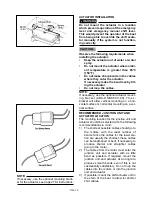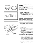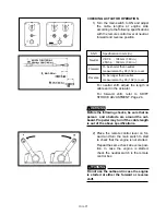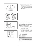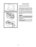
CONNECTING THE WIRE HARNESS
Length of the extension wire harness
should be 6m (20 ft.) or less.
Use of longer harness may cause defective
operation of the acutator.
1.
CONNECTING THE WIRE HARNESSES
FOR THE UPPER STATIONS
1) Feed the wire harness between the
first and second station. If may be nec-
essary to disconnect the individual bul-
let connectors located near the multi-
pin connectors for the second station.
Ensure that the proper wire color codes are
maintained when reconnecting the individ-
ual bullet connectors or improper opera-
tion may result.
2) Connect the matching connectors for
the second station control, switch
panel, and instruments.
2.
CONNECTING THE WIRING FOR THE
LOWER STATION
1) Connect the matching connectors for
the first station control, switch panel,
and instruments.
2) Connect the matching connectors
between the dual station harness and
the engine wire harnesses.
3.
CONNECT THE SHIFT ACTUATOR AND
JUNCTION UNIT
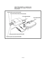
1) Connect the actuator main wire har-
ness between the dual station main
wire harness and the engine main wire
harness matching connector plugs.
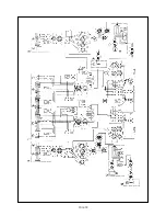
Connect the ten-pole connector to the
actuator unit.
2) Connect the three-pole connector
between the junction unit and the actu-
ator.
CAUTION:
CAUTION:
10A-23
Summary of Contents for T8
Page 2: ......
Page 9: ......
Page 35: ......
Page 37: ......
Page 61: ......
Page 63: ......
Page 65: ...2 2 Outboard Rigging Guide 2001 Engine Mounting Dimensions...
Page 67: ...2 4 Outboard Rigging Guide 2001 Engine Mounting Dimensions...
Page 71: ...2 8 Outboard Rigging Guide 2001 Transom Mounting Patterns 25HP 2 Cylinder...
Page 72: ...2 9 Outboard Rigging Guide 2001 Transom Mounting Patterns 25X3 3 Cyl 30HP 40HP Manual Tilt...
Page 109: ......
Page 111: ......
Page 128: ...3 17 Outboard Rigging Guide 2001 Switch Panels Oil Lamp Panel Assembly T9 9ELR 6G8 83530 00 00...
Page 155: ...3 44 Outboard Rigging Guide 2001 Boat Wiring Diagrams T9 9 with 703 Control...
Page 156: ...3 45 Outboard Rigging Guide 2001 T9 9 with Switch Panel...
Page 177: ...3 66 Outboard Rigging Guide 2001 After Market Dash Wiring...
Page 178: ...3 67 Outboard Rigging Guide 2001 COMPLETE BOAT WIRING DIAGRAMS 70 90HP F80 F115...
Page 179: ...3 68 Outboard Rigging Guide 2001 Complete Boat Wiring Diagrams V4 V6 Single Engine...
Page 180: ...3 69 Outboard Rigging Guide 2001 Complete Boat Wiring Diagrams V4 V6 Single Engine Cont d...
Page 181: ...3 70 Outboard Rigging Guide 2001 Complete Boat Wiring Diagrams V4 V6 F115 Dual Engine...
Page 182: ...3 71 Outboard Rigging Guide 2001 Complete Boat Wiring Diagrams V4 V6 F115 Dual Engine Cont d...
Page 183: ...3 72 Outboard Rigging Guide 2001 Complete Boat Wiring Diagrams V6 HPDI Single Engine...
Page 184: ...3 73 Outboard Rigging Guide 2001 Complete Boat Wiring Diagrams V6 HPDI Dual Engine...
Page 185: ......
Page 187: ......
Page 236: ......
Page 242: ...5 5 Outboard Rigging Guide 2001 Tachometer Digital Multi function Tachometer...
Page 359: ...6C 2 Outboard Rigging Guide 2001 E FEATURES...
Page 376: ...7 15 Outboard Rigging Guide 2001 F15 F25 Remote Control Attach Kit REMOVAL...
Page 406: ...NOTES...
Page 407: ...NOTES...
Page 418: ...Outboards 6X1 DUAL STATION SYSTEM INSTALLATION MANUAL YAMAHA MOTOR CO LTD 6X1 28199 Y2 10A 1...
Page 423: ...10A 6 GENERAL INFORMATION WIRING AND COMPONENT PARTS Single engine system Second station...
Page 424: ...10A 7 Twin engine system Second station...
Page 453: ...WIRING DIAGRAM FIRST STATION Single engine 10A 36...
Page 454: ...SECOND STATION Single engine 10A 37...
Page 455: ...10A 38...
Page 456: ...10A 39...
Page 457: ...Outboards 6X1 DUAL STATION SYSTEM SERVICE GUIDE 10B 1...
Page 460: ...10B 4...
Page 462: ...10B 6 Outboard Rigging Guide 2001 EXTERNAL VIEW OUTLINE OF FEATURES...
Page 495: ...10B 39 Outboard Rigging Guide 2001...
Page 496: ...10B 40 Outboard Rigging Guide 2001...


