TESTING
• Dual Station controls must be tested after rigging. Improperly installed or adjusted com-
ponents could operate incorrectly, which would increase the chance for loss of control
and an accident.
• Test the operation with the boat properly supported on land.
• The engine must be off and the lanyard removed before performing this test. Remove the
spark plug caps to prevent engine starting. Otherwise, accident or injury could occur if
the engine starts while turning the propeller by hand.
After making any adjustment, always check to make sure the cable end is screwed in at least
8mm.
TESTING SHIFT OPERATION
When testing shift operation, use two people. With the engine off, and the lanyard and spark-plug
caps removed, turn the ignition ON. Position one person at the engine to rotate the propeller and
verify correct operation.
The second person should operate the controls.
NOTE:
Because shift operation is performed while the engine is not running, the clutch dog may not
engage the forward or reverse gear perfectly. The warning buzzer will sound after about four sec-
onds if the gear has not been engaged.
1.
Turn the main switch to ON and remove the engine stop switch lockplate from the stop
switch.
2.
Operate the first station in the following sequence and observe operation:
1) Shift
2) Shift to neutral
3) Shift to reverse
4) Shift to neutral
3.
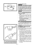
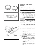
If incorrect operation is observed, make adjustments in the motor shift cable end at the
outboard motor.
4.
Operate the second station in the following sequence and observe operation:
1) Shift to forward
2) Shift to neutral
3) Shift to reverse
4) Shift to neutral
5.
If incorrect operation is observed at the second station, while the first station is oper-
ating correctly, make adjustments in the second station remote control shift cable at
the junction unit.
6.
Again operate the first station and repeat until correct operation is obtained.
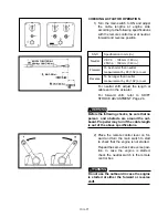
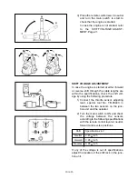
If correct operation is still not obtained, adjust the actuator by referring to the instructions in the
following CHECK AND ADJUSTMENTS.
CHECKING ACTUATOR OPERATION . . . . . . . . . . . . . . 10A-25
SHIFT VOLTAGE ADJUSTMENT . . . . . . . . . . . . . . . . . . 10A-26
SHIFT STROKE ADJUSTMENT . . . . . . . . . . . . . . . . . . 10A-30
WARNING
CAUTION:
10A-24
Summary of Contents for T8
Page 2: ......
Page 9: ......
Page 35: ......
Page 37: ......
Page 61: ......
Page 63: ......
Page 65: ...2 2 Outboard Rigging Guide 2001 Engine Mounting Dimensions...
Page 67: ...2 4 Outboard Rigging Guide 2001 Engine Mounting Dimensions...
Page 71: ...2 8 Outboard Rigging Guide 2001 Transom Mounting Patterns 25HP 2 Cylinder...
Page 72: ...2 9 Outboard Rigging Guide 2001 Transom Mounting Patterns 25X3 3 Cyl 30HP 40HP Manual Tilt...
Page 109: ......
Page 111: ......
Page 128: ...3 17 Outboard Rigging Guide 2001 Switch Panels Oil Lamp Panel Assembly T9 9ELR 6G8 83530 00 00...
Page 155: ...3 44 Outboard Rigging Guide 2001 Boat Wiring Diagrams T9 9 with 703 Control...
Page 156: ...3 45 Outboard Rigging Guide 2001 T9 9 with Switch Panel...
Page 177: ...3 66 Outboard Rigging Guide 2001 After Market Dash Wiring...
Page 178: ...3 67 Outboard Rigging Guide 2001 COMPLETE BOAT WIRING DIAGRAMS 70 90HP F80 F115...
Page 179: ...3 68 Outboard Rigging Guide 2001 Complete Boat Wiring Diagrams V4 V6 Single Engine...
Page 180: ...3 69 Outboard Rigging Guide 2001 Complete Boat Wiring Diagrams V4 V6 Single Engine Cont d...
Page 181: ...3 70 Outboard Rigging Guide 2001 Complete Boat Wiring Diagrams V4 V6 F115 Dual Engine...
Page 182: ...3 71 Outboard Rigging Guide 2001 Complete Boat Wiring Diagrams V4 V6 F115 Dual Engine Cont d...
Page 183: ...3 72 Outboard Rigging Guide 2001 Complete Boat Wiring Diagrams V6 HPDI Single Engine...
Page 184: ...3 73 Outboard Rigging Guide 2001 Complete Boat Wiring Diagrams V6 HPDI Dual Engine...
Page 185: ......
Page 187: ......
Page 236: ......
Page 242: ...5 5 Outboard Rigging Guide 2001 Tachometer Digital Multi function Tachometer...
Page 359: ...6C 2 Outboard Rigging Guide 2001 E FEATURES...
Page 376: ...7 15 Outboard Rigging Guide 2001 F15 F25 Remote Control Attach Kit REMOVAL...
Page 406: ...NOTES...
Page 407: ...NOTES...
Page 418: ...Outboards 6X1 DUAL STATION SYSTEM INSTALLATION MANUAL YAMAHA MOTOR CO LTD 6X1 28199 Y2 10A 1...
Page 423: ...10A 6 GENERAL INFORMATION WIRING AND COMPONENT PARTS Single engine system Second station...
Page 424: ...10A 7 Twin engine system Second station...
Page 453: ...WIRING DIAGRAM FIRST STATION Single engine 10A 36...
Page 454: ...SECOND STATION Single engine 10A 37...
Page 455: ...10A 38...
Page 456: ...10A 39...
Page 457: ...Outboards 6X1 DUAL STATION SYSTEM SERVICE GUIDE 10B 1...
Page 460: ...10B 4...
Page 462: ...10B 6 Outboard Rigging Guide 2001 EXTERNAL VIEW OUTLINE OF FEATURES...
Page 495: ...10B 39 Outboard Rigging Guide 2001...
Page 496: ...10B 40 Outboard Rigging Guide 2001...


