4-57
A
B
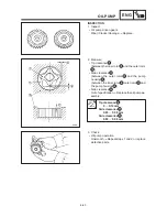
CRANKSHAFT
ENG
NOTE:
CAUTION:
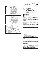
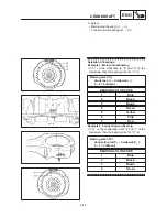
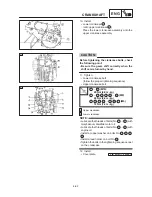
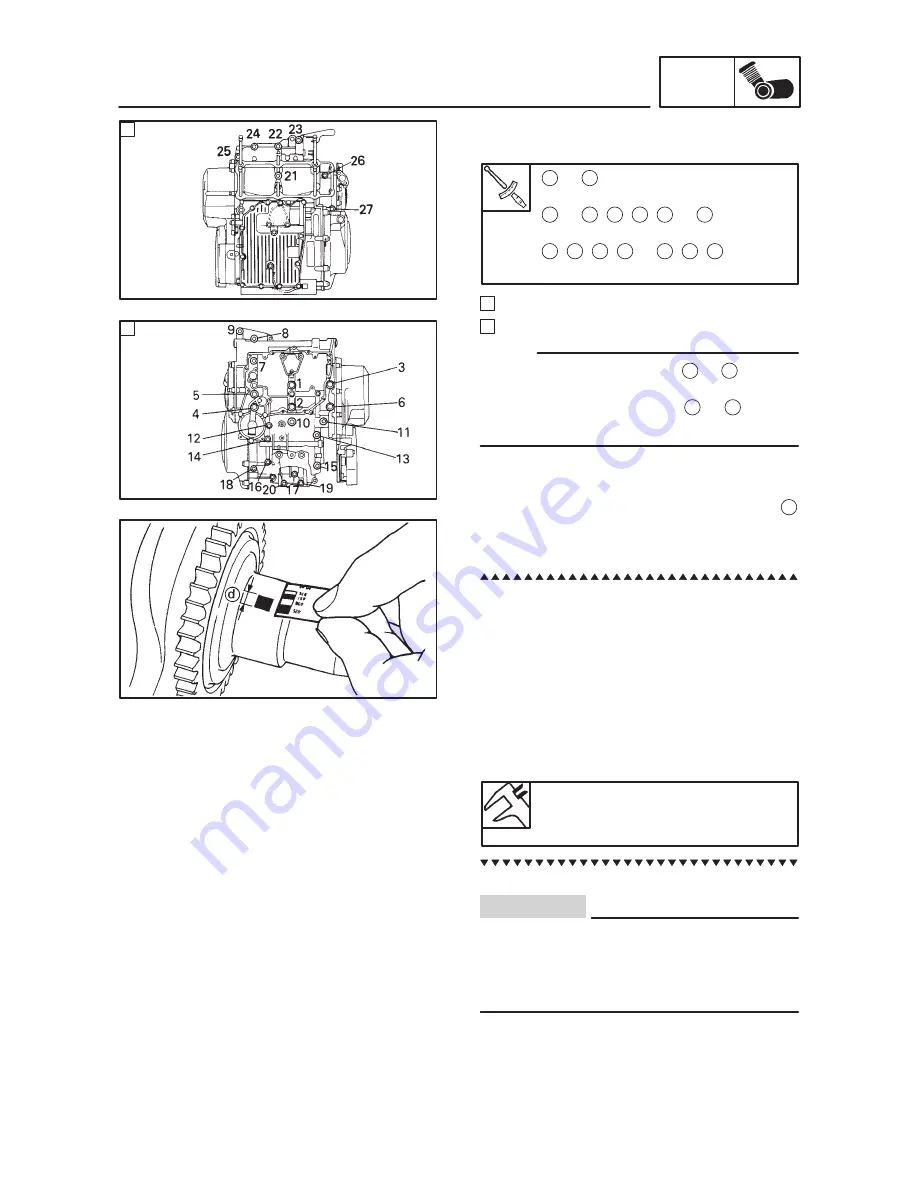
Tighten the bolt to specification in the tighten-
ing sequence cast on the crankcase.
1
6 (M10):
40 Nm (4.0 m
kg)
7
10
,
13
,
15
,
20
25
(M8)
24 Nm (2.4 m
kg)
11
,
12
,
14
,
16
19
,
26
,
27
(M6)
12 Nm (1.2 m
kg)
A
Upper crankcase
B
Lower crankcase
Lubricate the threads of bolts 1
6 with mo-
lybdenum disulfide motor oil.
Lubricate the threads of bolts 7
27
with en-
gine oil.
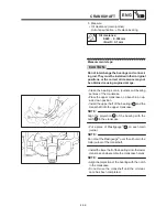
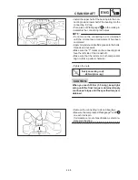
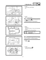
Remove the lower crankcase and lower half of
the bearing.
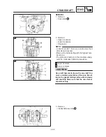
Measure the compressed Plastigauge
width d
on each main journal.
If oil clearance is out of specification, select a re-
placement bearing.
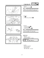
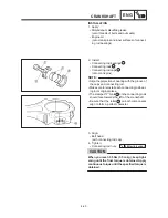
4. Measure:
Oil clearance (crank pin)
Out of specification
Replace bearing.
Oil clearance:
0.020
0.038 mm
<Limit>: 0.1 mm
Measurement steps:
Do not interchange the bearings and connect-
ing rod. They must be installed in their original
positions, or the correct oil clearance may not
be obtained causing engine damage.
Clean the bearings, crank pins and bearing
portions of the connecting rods.
Summary of Contents for TDM850 1996
Page 1: ......
Page 2: ......
Page 8: ......
Page 9: ...GEN INFO 1 ...
Page 11: ...GEN INFO ...
Page 20: ...SPEC 2 ...
Page 22: ...SPEC ...
Page 45: ...2 23 LUBRICATION DIAGRAMS SPEC 1 Cylinder head 2 Rear balancer 3 Crankshaft 4 Drain bolt ...
Page 46: ...2 24 LUBRICATION DIAGRAMS SPEC 1 Main axle 2 Drive axle ...
Page 56: ...SPEC ...
Page 57: ...INSP ADJ 3 ...
Page 121: ...INSP ADJ ...
Page 122: ...ENG 4 ...
Page 192: ...ENG ...
Page 193: ...COOL 5 ...
Page 195: ...COOL ...
Page 204: ...CARB 6 ...
Page 206: ...CARB ...
Page 214: ...CARB ...
Page 215: ...CHAS 7 ...
Page 273: ...CHAS ...
Page 274: ...ELEC 8 ...
Page 276: ...ELEC ...
Page 306: ...8 30 LIGHTING SYSTEM ELEC ...
Page 307: ...8 31 SIGNAL SYSTEM ELEC SIGNAL SYSTEM CIRCUIT DIAGRAM ...
Page 322: ...ELEC ...
Page 323: ...TRBL SHTG 9 ...
Page 325: ...TRBL SHTG ...

