3-7
VALVE CLEARANCE ADJUSTMENT
INSP
ADJ
NOTE:
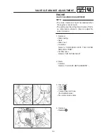
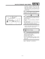
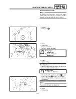
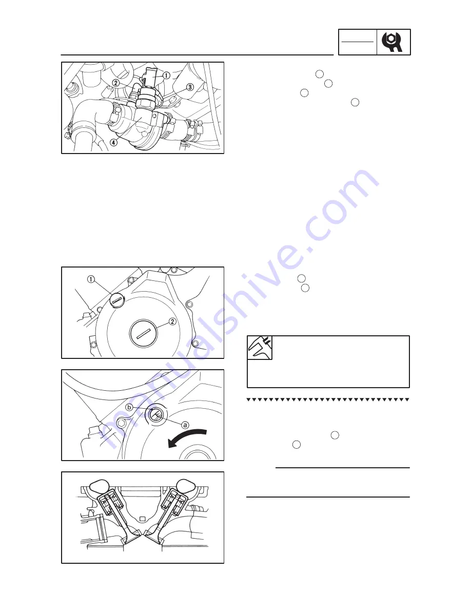
5. Disconnect:
Thermo unit lead 1
Thermo switch lead 2
Ground lead 3
Thermostatic valve housing 4
6. Remove:
Spark plug caps
Spark plugs
Cylinder head cover
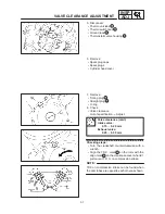
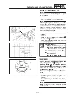
7. Remove:
Timing plug 1
Straight plug 2
O-ring
8. Check:
Valve clearance
Out of specification
Adjust.
Valve clearance (cold):
Intake valve:
0.15
0.20 mm
Exhaust valve:
0.25
0.30 mm
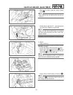
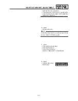
Checking steps:
Turn the crankshaft counterclockwise with a
wrench.
Align the T.D.C. mark a on the rotor with the
align mark b on the crankcase cover when #1
piston is at T.D.C. on compression stroke.
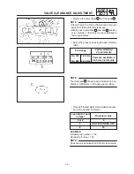
TDC on compression stroke can be found when
the cam lobes are opposite each other as shown.
Summary of Contents for TDM850 1996
Page 1: ......
Page 2: ......
Page 8: ......
Page 9: ...GEN INFO 1 ...
Page 11: ...GEN INFO ...
Page 20: ...SPEC 2 ...
Page 22: ...SPEC ...
Page 45: ...2 23 LUBRICATION DIAGRAMS SPEC 1 Cylinder head 2 Rear balancer 3 Crankshaft 4 Drain bolt ...
Page 46: ...2 24 LUBRICATION DIAGRAMS SPEC 1 Main axle 2 Drive axle ...
Page 56: ...SPEC ...
Page 57: ...INSP ADJ 3 ...
Page 121: ...INSP ADJ ...
Page 122: ...ENG 4 ...
Page 192: ...ENG ...
Page 193: ...COOL 5 ...
Page 195: ...COOL ...
Page 204: ...CARB 6 ...
Page 206: ...CARB ...
Page 214: ...CARB ...
Page 215: ...CHAS 7 ...
Page 273: ...CHAS ...
Page 274: ...ELEC 8 ...
Page 276: ...ELEC ...
Page 306: ...8 30 LIGHTING SYSTEM ELEC ...
Page 307: ...8 31 SIGNAL SYSTEM ELEC SIGNAL SYSTEM CIRCUIT DIAGRAM ...
Page 322: ...ELEC ...
Page 323: ...TRBL SHTG 9 ...
Page 325: ...TRBL SHTG ...

