background image

Periodic maintenance and adjustment

6-3

6

EAU71033

Periodic maintenance charts

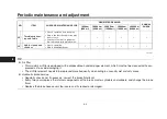
TIP

z

Items marked with an asterisk should be performed by your Yamaha dealer because these items require special tools,
data, and technical skills.

z

From 50000 km (30000 mi), repeat the maintenance intervals starting from 10000 km (6000 mi).

z

The annual checks must be performed every year, except if a distance-based maintenance is performed in-
stead.

EAU71051

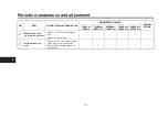
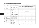
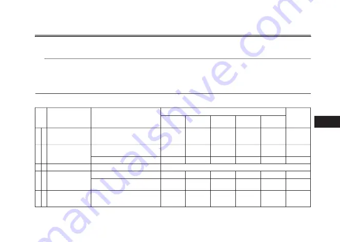
Periodic maintenance chart for the emission control system

NO.

ITEM

CHECK OR MAINTENANCE JOB

ODOMETER READING

ANNUAL 

CHECK

1000 km 

(600 mi)

10000 km 

(6000 mi)

20000 km 

(12000 mi)

30000 km 

(18000 mi)

40000 km 

(24000 mi)

1

*

Fuel line

t

Check fuel hoses for cracks or 
damage.

t

Replace if necessary.

2

*

Spark plugs

t

Check condition.

t

Adjust gap and clean.

t

Replace.

3

*

Valve clearance

)

i

m


0

0

0

4

2

(


m

k


0

0

0

0

4


y

r

e

v

E

.

t

s

u

j

d

a


d

n

a


k

c

e

h

C

t

4

*

Fuel injection

t

Check engine idle speed.

t

Check and adjust synchroniza-
tion.

5

*

Exhaust system

t

Check for leakage.

t

Tighten if necessary.

t

Replace gaskets if necessary.

Summary of Contents for Tracer MTT850D 2019

Page 1: ...OWNER S MANUAL Read this manual carefully before operating this vehicle MTT850D B0S F8199 30 ...

Page 2: ...this vehicle This manual should stay with this vehicle if it is sold EAU46091 EAU46091 䘉 অ䖖ԕࡽˈ䈧 ݵ 䘉ሿ DŽ䘉 享Ԉо অ䖖а䎧DŽ EAU46091 Baca buku panduan dengan teliti sebelum mengendalikan motosikal ini Buku panduan diberi bersama dengan pembelian motosikal ...

Page 3: ......

Page 4: ...s from trouble and injury In addition the many tips given in this manual will help keep your motorcycle in the best possible condition If you have any further questions do not hesitate to contact your Yamaha dealer The Yamaha team wishes you many safe and pleasant rides So remember to put safety first Yamaha continually seeks advancements in product design and quality Therefore while this manual c...

Page 5: ... used to alert you to potential personal injury hazards Obey all safety messages that follow this symbol to avoid possible injury or death A WARNING indicates a hazardous situation which if not avoided could result in death or serious injury A NOTICE indicates special precautions that must be taken to avoid damage to the vehicle or other property A TIP provides key information to make procedures e...

Page 6: ...0201 MTT850D OWNER S MANUAL 2018 by Yamaha Motor Co Ltd 1st edition December 2018 All rights reserved Any reprinting or unauthorized use without the written permission of Yamaha Motor Co Ltd is expressly prohibited Printed in Malaysia ...

Page 7: ...tand 3 44 Ignition circuit cut off system 3 45 For your safety pre operation checks 4 1 Operation and important riding points 5 1 Starting the engine 5 1 Shifting 5 2 Tips for reducing fuel consumption 5 3 Engine break in 5 3 Parking 5 4 Periodic maintenance and adjustment 6 1 Tool kit 6 2 Periodic maintenance charts 6 3 Periodic maintenance chart for the emission control system 6 3 General mainte...

Page 8: ...ont fork 6 28 Checking the steering 6 29 Checking the wheel bearings 6 29 Battery 6 29 Replacing the fuses 6 31 Headlights 6 33 Auxiliary lights 6 33 Brake tail light 6 33 Replacing a turn signal light bulb 6 34 Replacing the license plate light bulb 6 34 Troubleshooting 6 35 Troubleshooting charts 6 36 Motorcycle care and storage 7 1 Matte color caution 7 1 Care 7 1 Storage 7 4 Specifications 8 1...

Page 9: ...raining courses nearest you Safe Riding Perform the pre operation checks each time you use the vehicle to make sure it is in safe operating condition Failure to inspect or maintain the vehi cle properly increases the possibility of an accident or equipment damage See page 4 1 for a list of pre operation checks z This motorcycle is designed to carry the operator and a passen ger z The failure of mo...

Page 10: ... rests during operation to main tain control of the motorcycle t The passenger should always hold onto the operator the seat strap or grab bar if equipped with both hands and keep both feet on the passenger footrests Never carry a passenger unless he or she can firmly place both feet on the passenger footrests z Never ride under the influence of alcohol or other drugs z This motorcycle is designed...

Page 11: ...f the weight distribu tion of the motorcycle is changed To avoid the possibility of an accident use extreme caution when adding cargo or accessories to your motorcycle Use extra care when riding a motorcycle that has added cargo or accessories Here along with the information about accessories below are some general guidelines to follow if loading cargo to your motorcycle The total weight of the op...

Page 12: ...le that change any of the vehicle s design or operation characteristics can put you and others at greater risk of serious injury or death You are responsible for injuries related to changes in the vehicle Keep the following guidelines in mind as well as those provided under Load ing when mounting accessories z Never install accessories or carry cargo that would impair the per formance of your moto...

Page 13: ...and replacing your tires Transporting the Motorcycle Be sure to observe following instruc tions before transporting the motorcy cle in another vehicle z Remove all loose items from the motorcycle z Check that the fuel cock if equipped is in the off position and that there are no fuel leaks z Shift the transmission into gear for models with a manual trans mission z Secure the motorcycle with tie do...

Page 14: ...Battery page 6 29 3 Fuses page 6 31 4 Storage compartment page 3 38 5 Tool kit page 6 2 6 Seat lock page 3 34 7 Spring preload adjuster page 3 41 8 Rebound damping force adjuster page 3 41 9 Shift pedal page 3 26 10 Engine oil drain bolt page 6 11 11 Engine oil filter cartridge page 6 11 ...

Page 15: ...k cap page 3 30 3 Rebound damping force adjuster page 3 39 4 Spring preload adjuster page 3 39 5 Compression damping force adjuster page 3 39 6 Headlight page 6 33 7 Fuses page 6 31 8 Coolant reservoir page 6 13 9 Engine oil level check window page 6 11 10 Engine oil filler cap page 6 11 11 Brake pedal page 3 27 ...

Page 16: ...ge 3 25 2 Left handlebar switches page 3 3 3 Auxiliary DC jack page 3 43 4 Instrument panel page 3 5 3 11 5 Front brake fluid reservoir page 6 21 6 Right handlebar switches page 3 3 7 Brake lever page 3 26 8 Throttle grip page 6 15 9 Grip warmer page 3 14 10 Main switch steering lock page 3 2 ...

Page 17: ...ard key for driving TIP z Keep the standard keys as well as keys of other immobilizer systems away from the code re registering key z Keep other immobilizer system keys away from the main switch as they may cause signal interfer ence NOTICE ECA11823 DO NOT LOSE THE CODE RE REG ISTERING KEY CONTACT YOUR DEALER IMMEDIATELY IF IT IS LOST If the code re registering key is lost the existing standard ke...

Page 18: ...gine can be started The key cannot be removed TIP z The headlight s will turn on when the engine is started z To prevent battery drain do not leave the key in the on position without the engine running EAU10662 OFF All electrical systems are off The key can be removed WARNING EWA10062 Never turn the key to OFF or LOCK while the vehicle is moving Otherwise the electrical systems will be switched of...

Page 19: ...can be turned on but all other electri cal systems are off The key can be re moved The steering must be locked before the key can be turned to NOTICE ECA20760 Using the hazard or turn signal lights for an extended length of time may cause the battery to discharge EAU66055 Handlebar switches Left 1 2 1 Drive mode switch MODE 2 TCS switch 3 Cruise control switches 4 Hazard switch 5 Horn switch 6 Tur...

Page 20: ...hen the vehicle overturns or when the throttle cable is stuck EAU66010 Hazard switch With the key in the ON or posi tion use this switch to turn on the haz ard lights simultaneous flashing of all turn signal lights The hazard lights are used in case of an emergency or to warn other drivers when your vehicle is stopped where it might be a traffic hazard NOTICE ECA10062 Do not use the hazard lights ...

Page 21: ...s indicator light comes on when the transmission is in the neutral position EAU11081 High beam indicator light This indicator light comes on when the high beam of the headlight is switched on EAU58402 Cruise control indicator lights and SET These indicator lights come on when the cruise control system is activated See page 3 8 TIP When the vehicle is turned on these lights should come on for a few...

Page 22: ...hile riding the brake system re verts to conventional braking If ei ther of the above occurs or if the warning light does not come on at all use extra caution to avoid possi ble wheel lock during emergency braking Have a Yamaha dealer check the brake system and electri cal circuits as soon as possible EAU73272 Traction control system indicator light In normal operation this indicator light is off ...

Page 23: ... sure there are no other im mobilizer keys close to the main switch Other immobilizer system keys may cause signal interfer ence and prevent the engine from starting 2 Use the code re registering key to start the engine 3 If the engine starts turn it off and try starting the engine with the standard keys 4 If one or both of the standard keys do not start the engine take the vehicle and all 3 keys ...

Page 24: ... EWA16341 z Improper use of the cruise con trol system may result in loss of control which could lead to an accident Do not activate the cruise control system in heavy traffic poor weather conditions or among winding slippery hilly rough or gravel roads z When traveling uphill or down hill the cruise control system may not be able to maintain the set cruising speed z To prevent accidentally activa...

Page 25: ...f ap proximately 2 0 km h 1 2 mi h Hold ing the RES or SET side of the cruise control setting switch down will increase or decrease the speed contin uously until the switch is released You can also manually increase your traveling speed using the throttle After you have accelerated you can set a new cruising speed by pushing the SET side of the setting switch If you do not set a new cruising speed...

Page 26: ...cruise control system will auto matically become deactivated under the following conditions z The cruise control system is not able to maintain the set cruising speed z Wheel slip or wheel spin is detect ed If the traction control system has not been turned off the trac tion control system will work z The start engine stop switch is set to the position z The engine stalls z The sidestand is lowere...

Page 27: ...play z Air temperature display z Grip warmer display z QS indicator z Clock z Revolution peak hold indicator z Eco indicator z Fuel level warning icon z Engine oil warning icon z Coolant temperature warning icon TIP This model uses a thin film transistor liquid crystal display TFT LCD for good contrast and readability in vari ous lighting conditions However due to the nature of this technology it ...

Page 28: ...tes the amount of fuel in the fuel tank The display seg ments of the fuel meter disappear from F full towards E empty as the fuel level decreases When the last segment starts flashing and the fuel level warning icon comes on refuel as soon as possible TIP If all the fuel meter display segments flash repeatedly have a Yamaha deal er check the related circuits Clock The clock uses a 12 hour time sys...

Page 29: ...s and a neutral position The neutral position is indicated by the neutral indicator light and by the transmission gear display Revolution peak hold indicator This small bar momentarily appears within the tachometer to mark the most recent peak r min speed of the engine TIP The indicator comes on momentarily only if the peak engine speed is 7000 r min or higher QS indicator When the key is turned t...

Page 30: ...h the wheel switch and then rotate the wheel switch up or down to change the setting while the display is flashing Short push the wheel switch to confirm the setting TIP Each grip warmer setting can be fine tuned in Grip Warmer Setting see page 3 23 NOTICE ECA17932 z Be sure to wear gloves when using the grip warmers z Do not use the grip warmers in warm weather z If the handlebar grip or throttle...

Page 31: ...tch operations are common operations for accessing selecting and moving within the MENU screen and its modules Long push press and hold the wheel switch for one second to access the MENU screen or exit MENU entirely Select rotate the wheel switch up or down to highlight the desired module or setting item and then short push the wheel switch briefly press the wheel switch inward to confirm the sele...

Page 32: ... From the MENU screen select Maintenance 2 Select the item you want to reset 3 Long push the wheel switch to re set the item TIP Maintenance item names cannot be changed Unit This module allows you to switch the display between kilometers and miles When using kilometers the fuel con sumption units can be changed be tween km L or L 100km When using miles MPG will be available To set the distance or...

Page 33: ...ing con ditions and will automatically change the display between its day and night settings The photo sensor also con trols a subtle automatic brightness ad justment function within both the day and night modes to suit ambient light conditions To set the wallpaper 1 From the MENU screen select Wallpaper 2 Select the mode you want to ad just select DAY for daytime dis play settings or NIGHT for ni...

Page 34: ... GPS 12 00 BLACK Display Description Set the shift indicator pat tern to ON Flash or OFF and adjust at what r min the indicator will come on and go off Adjust the brightness of the shift indicator Set the tachometer color display to ON or OFF and adjust at what r min the tachometer will be green and orange Set the tachometer revolu tion peak hold indicator to ON or OFF Shift IND Setting Shift IND ...

Page 35: ...ness then use the wheel switch to adjust the setting Short push the wheel switch to confirm the setting and exit Tach IND Setting This module allows you to turn the ta chometer color display on or off When turned off the tachometer will display all r min levels below the red zone in 1000 r min 12 00 Shift IND Setting IND Mode IND Start IND Stop ON 6000 r min 12000 r min km h Shift Indicator 1000 r...

Page 36: ...layed in green TIP Green bar start setting range 5000 11300 r min 6 Select Tach IND 2nd 12 00 Shift Indicator km h Tach IND Setting Shift IND Setting Peak Rev IND Setting Shift IND Brightness 1000 r min 12 00 km h Shift Indicator Tach IND Setting IND Mode ON 5000 r min 8000 r min Tach IND 1st Tach IND 2nd 1000 r min 12 00 km h Shift Indicator Tach IND Setting IND Mode ON 5000 r min 8000 r min Tach...

Page 37: ...splay Setting This module allows you to set how the information display items like TRIP 1 ODO C TEMP etc are grouped on the main screen There are four display groups To set the display groups 1 From the MENU screen select Display Setting 1000 r min 12 00 km h Shift Indicator Tach IND Setting IND Mode ON 5000 r min 8000 r min Tach IND 1st Tach IND 2nd 1000 r min 12 00 km h Shift Indicator Tach IND ...

Page 38: ...tion z CRNT FUEL current fuel con sumption 6 Select 1 2 to set the remaining DISPLAY 1 group item 7 Select the triangle symbol to exit To set the other display groups repeat from step 3 Brightness This module allows you to adjust the general brightness level of the display screen To set the brightness 1 From the MENU screen select Brightness 12 00 MENU km h Brightness Display Setting Shift Indicat...

Page 39: ... 4 To set the temperature level for another grip warmer setting re peat from step 2 or select the tri angle symbol to exit this module Clock This module allows you to set the clock To set the clock 1 From the MENU screen select Clock 12 00 MENU km h Brightness Display Setting Shift Indicator Wallpaper Unit Maintenance Brightness 12 00 km h Brightness 2 12 00 MENU km h All Reset Clock Grip Warmer S...

Page 40: ...in to exit and go back to the MENU screen All Reset This module contains the all reset func tion which resets everything except the odometer and clock to its factory preset or default setting Select YES to reset all items After se lecting YES all items will be reset and the display will automatically return to the MENU screen 12 00 MENU km h All Reset Clock Grip Warmer Setting Brightness Display S...

Page 41: ... the high speed range Mode A Mode A offers a sportier engine re sponse in the low to mid speed range compared to mode STD Mode B Mode B offers response that is somewhat less sharp compared to mode STD for riding situations that require especially sensitive throttle op eration EAU12822 Clutch lever The clutch lever is located on the left side of the handlebar To disengage the clutch pull the lever ...

Page 42: ...rily adjusted to al low the upshift to occur TIP z The quick shift system operates when traveling at least 20 km h 12 mi h with an engine speed of 2300 r min or higher and only when accelerating z It does not operate when the clutch lever is pulled EAU26826 Brake lever The brake lever is located on the right side of the handlebar To apply the front brake pull the lever toward the throttle grip The...

Page 43: ... best with long braking distances z On certain surfaces such as rough or gravel roads the brak ing distance may be longer with the ABS than without The ABS is monitored by an ECU which will revert the system to conven tional braking if a malfunction occurs TIP z The ABS performs a self diagno sis test each time the vehicle first starts off after the key is turned to ON and the vehicle has traveled...

Page 44: ...e speed when entering turns when accelerating hard at a sharp lean angle or while braking and cannot prevent front wheel slip ping As with any vehicle approach surfaces that may be slippery with caution and avoid especially slip pery surfaces The indicator light flashes when traction control has engaged You may notice slight changes in engine and ex haust sounds when the system has en gaged 1 Fron...

Page 45: ...e traction control system WARNING EWA15441 Be sure to stop the vehicle before making any setting changes to the traction control system Changing settings while riding can distract the operator and increase the risk of an accident TCS settings can be changed only when the vehicle is stopped and the throttle closed z Push the TCS switch to change the TCS setting to TCS 1 and push the TCS switch to c...

Page 46: ...cle and turn off the warning light EAU13076 Fuel tank cap To open the fuel tank cap Open the fuel tank cap lock cover in sert the key into the lock and then turn it 1 4 turn clockwise The lock will be released and the fuel tank cap can be opened To close the fuel tank cap With the key still inserted in the lock push down the fuel tank cap Turn the key 1 4 turn counterclockwise remove it and then c...

Page 47: ...er refuel while smoking or while in the vi cinity of sparks open flames or other sources of ignition such as the pilot lights of water heaters and clothes dryers 2 Do not overfill the fuel tank When refueling be sure to insert the pump nozzle into the fuel tank filler hole Stop filling when the fuel reaches the bottom of the filler tube Because fuel expands when it heats up heat from the engine or...

Page 48: ...research octane number of 95 or higher If knocking or pinging occurs use a gasoline of a different brand Use of unleaded fuel will extend spark plug life and reduce mainte nance costs Gasohol There are two types of gasohol gaso hol containing ethanol and that con taining methanol Gasohol containing ethanol can be used if the ethanol con tent does not exceed 10 E10 Gas ohol containing methanol is n...

Page 49: ...ot after op eration To prevent a fire hazard or burns z Do not park the vehicle near possible fire hazards such as grass or other materials that easily burn z Park the vehicle in a place where pedestrians or children are not likely to touch the hot exhaust system z Make sure that the exhaust sys tem has cooled down before doing any maintenance work z Do not allow the engine to idle more than a few...

Page 50: ...of the seat down to lock it in place 2 Remove the key Rider seat To remove the rider seat 1 Remove the passenger seat 2 Remove the cap then push the rider seat lock lever located under the back of the rider seat to the left as shown and then pull the seat off To install the rider seat 1 Install the cap with the arrow mark facing forward 2 Insert the projection on the front of the rider seat into t...

Page 51: ... rid er s preference The rider seat height was adjusted to the lower position at delivery To change the rider seat height to the high position 1 Remove the passenger seat and rider seat See page 3 34 2 Remove the rider seat height posi tion adjuster by pulling it upward 3 Install the rider seat height posi tion adjuster by inserting the front projections into the grommets 1 Projection 2 Seat holde...

Page 52: ...the low position 1 Remove the passenger seat and rider seat See page 3 34 2 Remove the rider seat height posi tion adjuster by pulling it upward 3 Install the rider seat height posi tion adjuster by inserting the rear projections into the grommets 4 Insert the projection on the front of the rider seat into seat holder A as shown 1 Projection 2 Seat holder B for high position 2 1 2 1 Projection 2 H...

Page 53: ...the helmet holder 1 Remove the passenger seat See page 3 34 2 Pass the helmet holding cable through the buckle on the helmet strap as shown and then hook the cable loops over the helmet hold er 3 Place the helmet on the right side of the vehicle and then install the seat WARNING Never ride with a helmet attached to the helmet holder since the helmet may hit objects causing loss of control and poss...

Page 54: ...up the windshield lock lever and slide the windshield up or down Release the lock lever when finished TIP Make sure the windshield and lock le ver are properly secured before riding EAU39612 Adjusting the headlight beams The headlight beam adjusting knobs are used to raise or lower the height of the headlight beams It may be neces sary to adjust the headlight beams to increase visibility and help ...

Page 55: ...usting screw and the left front fork leg with a com pression damping force adjusting screw NOTICE ECA10102 To avoid damaging the mechanism do not attempt to turn beyond the maximum or minimum settings Spring preload To increase the spring preload and thereby harden the suspension turn the adjusting bolt on each fork leg in di rection a To decrease the spring pre load and thereby soften the suspens...

Page 56: ...ompression damping force and there by soften the compression damping turn the adjusting screw in direction b TIP Be sure to perform this adjustment on the left front fork leg 1 1 Rebound damping force adjusting screw Rebound damping setting Minimum soft 11 click s in direction b Standard 7 click s in direction b Maximum hard 1 click s in direction b 1 a b Rebound damping force The rebound damping ...

Page 57: ...ock absorber assembly This shock absorber assembly is equipped with a spring preload adjust ing knob and a rebound damping force adjusting screw NOTICE ECA10102 To avoid damaging the mechanism do not attempt to turn beyond the maximum or minimum settings Spring preload To increase the spring preload and thereby harden the suspension turn the adjusting knob in direction a To decrease the spring pre...

Page 58: ...ive and may damage the suspension WARNING EWA10222 This shock absorber assembly con tains highly pressurized nitrogen gas Read and understand the fol lowing information before handling the shock absorber assembly z Do not tamper with or attempt to open the cylinder assembly z Do not subject the shock ab sorber assembly to an open flame or other high heat source This may cause the unit to ex plode ...

Page 59: ...be used with the engine turned off and the load must never exceed 24 W 2 A otherwise the fuse may blow or the battery may discharge To use the auxiliary DC jack 1 Turn the main switch off 2 Remove the auxiliary DC jack cap 3 Turn the accessory off 4 Insert the accessory plug into the auxiliary DC jack 5 Turn the main switch on and start the engine See page 5 1 6 Turn the accessory on WARNING EWA14...

Page 60: ...e ignition in certain situa tions See the following section for an explanation of the ignition circuit cut off system WARNING EWA10242 The vehicle must not be ridden with the sidestand down or if the side stand cannot be properly moved up or does not stay up otherwise the sidestand could contact the ground and distract the operator resulting in a possible loss of control Yamaha s ignition circuit ...

Page 61: ...lutch lever is pulled and the sidestand is up Also it will stop the running engine should the sidestand be lowered while the trans mission is in gear Periodically check this system via the following procedure TIP z This check is most reliable if per formed with a warmed up engine z See pages 3 2 and 3 3 for switch operation information ...

Page 62: ...ne stall After the engine has stalled 10 Move the sidestand up 11 Pull the clutch lever 12 Push the start switch Does the engine start The system is OK The motorcycle can be ridden YES NO YES NO YES NO The neutral switch may not be working The motorcycle should not be ridden until checked by a Yamaha dealer The clutch switch may not be working The motorcycle should not be ridden until checked by a...

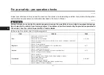
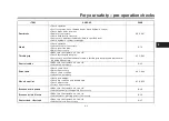
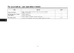
Page 63: ... following points E G A P S K C E H C M E T I Fuel t Check fuel level in fuel tank t Refuel if necessary t Check fuel line for leakage t Check fuel tank overflow hose for obstructions cracks or damage and check hose connection 3 31 3 33 Engine oil t Check oil level in engine t If necessary add recommended oil to specified level t Check vehicle for oil leakage 6 11 Coolant t Check coolant level in ...

Page 64: ...adjust throttle grip free play and lubricate ca ble and grip housing 6 15 6 25 Control cables t Make sure that operation is smooth t Lubricate if necessary 6 25 Drive chain t Check chain slack t Adjust if necessary t Check chain condition t Lubricate if necessary 6 23 6 24 Wheels and tires t Check for damage t Check tire condition and tread depth t Check air pressure t Correct if necessary 6 16 6 ...

Page 65: ...ws are properly tightened t Tighten if necessary Instruments lights signals and switches t Check operation t Correct if necessary Sidestand switch t Check operation of ignition circuit cut off system t If system is not working correctly have Yamaha dealer check vehicle 3 44 E G A P S K C E H C M E T I ...

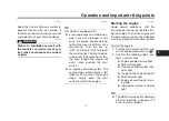
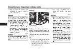
Page 66: ...ll crank when pushing the start switch z an engine auto stop system The engine stops automatically if left idling for 20 minutes If the engine stops simply push the start switch to restart the engine EAU84361 Starting the engine Under normal conditions shift the transmission into neutral before start ing the engine To start the engine with the transmission in gear the sidestand must be up and the ...

Page 67: ...ting off accelerating climbing hills etc The gear positions are shown in the il lustration TIP z To shift the transmission into the neutral position press the shift pedal down repeatedly until it reaches the end of its travel and then slightly raise it z This model is equipped with a quick shift system See page 3 26 NOTICE ECA23990 z Even with the transmission in the neutral position do not coast ...

Page 68: ... the fol lowing material carefully Since the engine is brand new do not put an excessive load on it for the first 1600 km 1000 mi The various parts in the engine wear and polish themselves to the correct operating clearances During this period prolonged full throt tle operation or any condition that might result in engine overheating must be avoided EAU17094 0 1000 km 0 600 mi Avoid prolonged oper...

Page 69: ...312 z Since the engine and exhaust system can become very hot park in a place where pedestri ans or children are not likely to touch them and be burned z Do not park on a slope or on soft ground otherwise the vehicle may overturn increasing the risk of a fuel leak and fire z Do not park near grass or other flammable materials which might catch fire ...

Page 70: ...urn off the engine when performing maintenance unless otherwise specified z A running engine has moving parts that can catch on body parts or clothing and electrical parts that can cause shocks or fires z Running the engine while ser vicing can lead to eye injury burns fire or carbon monoxide poisoning possibly leading to death See page 1 3 for more in formation about carbon monox ide WARNING EWA1...

Page 71: ...nd the tools provided in the tool kit are intended to assist you in the perfor mance of preventive maintenance and minor repairs However a torque wrench and other tools are necessary to perform certain maintenance work correctly TIP If you do not have the tools or experi ence required for a particular job have your Yamaha dealer perform it for you 1 Tool kit 1 1 1 ...

Page 72: ... stead EAU71051 Periodic maintenance chart for the emission control system NO ITEM CHECK OR MAINTENANCE JOB ODOMETER READING ANNUAL CHECK 1000 km 600 mi 10000 km 6000 mi 20000 km 12000 mi 30000 km 18000 mi 40000 km 24000 mi 1 Fuel line t Check fuel hoses for cracks or damage t Replace if necessary 2 Spark plugs t Check condition t Adjust gap and clean t Replace 3 Valve clearance i m 0 0 0 4 2 m k ...

Page 73: ...r dam age t Replace if necessary 7 Air induction sys tem t Check the air cut off valve reed valve and hose for damage t Replace any damaged parts if necessary NO ITEM CHECK OR MAINTENANCE JOB ODOMETER READING ANNUAL CHECK 1000 km 600 mi 10000 km 6000 mi 20000 km 12000 mi 30000 km 18000 mi 40000 km 24000 mi ...

Page 74: ...e c a l p e R t 3 Clutch t Check operation t Adjust 4 Front brake t Check operation fluid level and for fluid leakage t Replace brake pads if necessary 5 Rear brake t Check operation fluid level and for fluid leakage t Replace brake pads if necessary 6 Brake hoses t Check for cracks or damage s r a e y 4 y r e v E e c a l p e R t 7 Brake fluid s r a e y 2 y r e v E e g n a h C t 8 Wheels t Check r...

Page 75: ... for looseness t Moderately repack with lithium soap based grease 14 Chassis fasteners t Make sure that all nuts bolts and screws are properly tightened 15 Brake lever pivot shaft t Lubricate with silicone grease 16 Brake pedal pivot shaft t Lubricate with lithium soap based grease 17 Clutch lever pivot shaft t Lubricate with lithium soap based grease 18 Shift pedal pivot shaft t Lubricate with li...

Page 76: ...m pivoting points t Check operation 24 Engine oil t Change warm engine before draining t Check oil level and vehicle for oil leakage 25 Engine oil filter car tridge t Replace 26 Cooling system t Check coolant level and vehicle for coolant leakage s r a e y 3 y r e v E e g n a h C t 27 Front and rear brake switches t Check operation 28 Moving parts and cables t Lubricate NO ITEM CHECK OR MAINTENANC...

Page 77: ...uid level t Every two years replace the internal components of the brake master cylinders and calipers and change the brake fluid t Replace the brake hoses every four years and if cracked or damaged 29 Throttle grip hous ing and cable t Check operation and free play t Adjust the throttle cable free play if necessary t Lubricate the throttle grip hous ing cable and grip warmer wire 30 Lights signal...

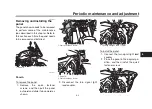
Page 78: ...installed EAU63101 Panel A To remove the panel 1 Remove the quick fastener screws and then pull the panel outward and slide it downward as shown 2 Disconnect the turn signal light lead coupler To install the panel 1 Connect the turn signal light lead coupler 2 Place the panel in the original po sition and then install the quick fastener screws 1 Panel A 1 1 Quick fastener screw 1 Panel A 2 Quick f...

Page 79: ... of elec trode erosion and excessive carbon or other deposits it should be replaced Before installing a spark plug the spark plug gap should be measured with a wire thickness gauge and if necessary adjusted to specification Clean the surface of the spark plug gasket and its mating surface and then wipe off any grime from the spark plug threads TIP If a torque wrench is not available when installin...

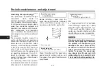
Page 80: ...cates the clutch do not mix any chemical additives Do not use oils with a diesel speci fication of CD or oils of a high er quality than specified In addition do not use oils labeled ENERGY CONSERVING II or higher z Make sure that no foreign mate rial enters the crankcase To check the engine oil level 1 After warming up the engine wait a few minutes for the oil to settle 2 With the vehicle on a lev...

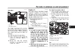
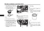
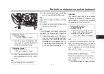
Page 81: ...he used oil 3 Remove the engine oil filler cap and then the engine oil drain bolt and gasket TIP Skip steps 4 6 if the oil filter cartridge is not being replaced 4 Remove the oil filter cartridge with an oil filter wrench TIP An oil filter wrench is available at a Yamaha dealer 5 Apply a thin coat of clean engine oil to the O ring of the new oil filter cartridge TIP Make sure that the O ring is pr...

Page 82: ...that the en gine oil level is sufficient ECA10012 EAUS1203 Coolant The coolant level should be checked regularly In addition the coolant must be changed at the intervals specified in the periodic maintenance chart TIP If genuine Yamaha coolant is not avail able use an ethylene glycol antifreeze containing corrosion inhibitors for alu minum engines and mix with distilled water at a 1 1 ratio EAU200...

Page 83: ... has been used instead of coolant replace it with cool ant as soon as possible other wise the cooling system will not be protected against frost and corrosion If water has been added to the coolant have a Yamaha dealer check the anti freeze content of the coolant as soon as possible otherwise the effectiveness of the coolant will be reduced ECA10473 5 Install the coolant reservoir cap EAU33032 Cha...

Page 84: ... element EAU44735 Checking the engine idling speed Check the engine idling speed and if necessary have it corrected by a Yamaha dealer EAU21386 Checking the throttle grip free play Measure the throttle grip free play as shown Periodically check the throttle grip free play and if necessary have a Yamaha dealer adjust it Engine idling speed 1100 1300 r min 1 Throttle grip free play Throttle grip fre...

Page 85: ... appropriate time with the speci fied tires Tire air pressure The tire air pressure should be checked and if necessary adjusted before each ride WARNING EWA10504 Operation of this vehicle with im proper tire pressure may cause se vere injury or death from loss of control z The tire air pressure must be checked and adjusted on cold tires i e when the temperature of the tires equals the ambient temp...

Page 86: ...d be left to a Yamaha dealer who has the necessary professional knowl edge and experience to do so z Ride at moderate speeds after changing a tire since the tire surface must first be broken in for it to develop its optimal characteristics Tire information This model is equipped with tubeless tires and tire air valves Tires age even if they have not been used or have only been used occasion ally C...

Page 87: ...eed riding to ride conserva tively for approximately 100 km 60 mi after installing a new tire z The tires must be warmed up before a high speed run z Always adjust the tire air pres sure according to the operating conditions EAU21963 Cast wheels To maximize the performance durabil ity and safe operation of your vehicle note the following points regarding the specified wheels z The wheel rims shoul...

Page 88: ... clutch does not operate correctly have a Yamaha dealer check the internal clutch mechanism EAU37914 Checking the brake lever free play There should be no free play at the brake lever end If there is free play have a Yamaha dealer inspect the brake system WARNING EWA14212 A soft or spongy feeling in the brake lever can indicate the presence of air in the hydraulic system If there is air in the hyd...

Page 89: ...should only be serviced by a Yamaha dealer EAU22393 Checking the front and rear brake pads The front and rear brake pads must be checked for wear at the intervals spec ified in the periodic maintenance and lubrication chart EAU36891 Front brake pads Each front brake pad is provided with wear indicators which allows you to check the brake pad wear without hav ing to disassemble the brake To check t...

Page 90: ...e brake pads as a set EAU40262 Checking the brake fluid level Before riding check that the brake fluid is above the minimum level mark Check the brake fluid level with the top of the reservoir level Replenish the brake fluid if necessary Front brake Rear brake WARNING EWA16011 Improper maintenance can result in loss of braking ability Observe these precautions z Insufficient brake fluid may al low...

Page 91: ...urfaces or plastic parts Always clean up spilled fluid immediately As the brake pads wear it is normal for the brake fluid level to gradually go down A low brake fluid level may indi cate worn brake pads and or brake system leakage therefore be sure to check the brake pads for wear and the brake system for leakage If the brake fluid level goes down suddenly have a Yamaha dealer check the cause bef...

Page 92: ... 97 in the chain can dam age the frame swingarm and other parts To prevent this from occurring keep the drive chain slack within the specified limits ECA17791 EAU63122 To adjust the drive chain slack Consult a Yamaha dealer before ad justing the drive chain slack 1 Take the motorcycle off the cen terstand and then put the side stand down 2 Loosen the axle nut and the lock nut on each side of the s...

Page 93: ...ive chain must be cleaned and lubricated at the intervals specified in the periodic maintenance and lubrica tion chart otherwise it will quickly wear out especially when riding in dusty or wet areas Service the drive chain as follows NOTICE ECA10584 The drive chain must be lubricated after washing the motorcycle riding in the rain or riding in wet areas 1 Clean the drive chain with kero sene and a...

Page 94: ... lubricating the throttle grip and cable The operation of the throttle grip should be checked before each ride In addition the cable should be lubricat ed by a Yamaha dealer at the intervals specified in the periodic maintenance chart The throttle cable is equipped with a rubber cover Make sure that the cover is securely installed Even though the cover is installed correctly it does not completely...

Page 95: ...before each ride and the pedal pivots should be lu bricated if necessary Brake pedal Shift pedal EAU23144 Checking and lubricating the brake and clutch levers The operation of the brake and clutch levers should be checked before each ride and the lever pivots should be lu bricated if necessary Brake lever Clutch lever Recommended lubricant Lithium soap based grease ...

Page 96: ...rfaces should be lubri cated if necessary WARNING EWA10742 If the centerstand or sidestand does not move up and down smoothly have a Yamaha dealer check or re pair it Otherwise the centerstand or sidestand could contact the ground and distract the operator resulting in a possible loss of control Recommended lubricants Brake lever Silicone grease Clutch lever Lithium soap based grease Recommended l...

Page 97: ...o check the condition Check the inner tubes for scratches damage and excessive oil leakage To check the operation 1 Place the vehicle on a level sur face and hold it in an upright posi tion WARNING To avoid injury securely support the vehicle so there is no danger of it falling over EWA10752 2 While applying the front brake push down hard on the handle bars several times to check if the front fork...

Page 98: ...or repair the steer ing EAU23292 Checking the wheel bearings The front and rear wheel bearings must be checked at the intervals specified in the periodic maintenance and lubrica tion chart If there is play in the wheel hub or if the wheel does not turn smoothly have a Yamaha dealer check the wheel bearings EAU50212 Battery The battery is located under the rider seat See page 3 34 This model is equ...

Page 99: ...trical accessories NOTICE ECA16522 To charge a VRLA Valve Regulated Lead Acid battery a special con stant voltage battery charger is re quired Using a conventional battery charger will damage the battery To store the battery 1 If the vehicle will not be used for more than one month remove the battery fully charge it and then place it in a cool dry place NOTICE When removing the battery be sure to ...

Page 100: ...ection system fuse remove the starter relay cover by pulling it upward To access fuse box 2 and fuse box 3 remove panel A See page 6 9 1 Fuse box 1 2 Main fuse 3 Fuel injection system fuse 4 Fuel injection system spare fuse 1 3 4 2 1 Radiator fan motor fuse 2 Backup fuse for clock and immobilizer sys tem 3 Electronic throttle valve fuse 4 ABS solenoid fuse 5 ABS motor fuse 6 Spare fuse 1 2 3 4 5 6...

Page 101: ...dlight fuse 3 Plug 12V fuse DC connector option 4 Plug 12V fuse DC jack 5 Cruise control fuse 6 Brake light fuse 7 Signaling system fuse 8 Fog lamp fuse option 9 ABS control unit fuse 10 Seat heater fuse option 11 Spare fuse 12 Ignition fuse 1 2 3 4 11 12 11 10 9 8 7 6 5 Specified fuses Main fuse 50 0 A Fuel injection system fuse 20 0 A Specified fuses fuse box 1 Radiator fan motor fuse 15 0 A ABS...

Page 102: ...s are set to high beam or the passing switch is pushed both headlights should come on NOTICE ECA16581 Do not affix any type of tinted film or stickers to the headlight lens EAU54502 Auxiliary lights This model is equipped with LED type auxiliary lights If an auxiliary light does not come on have a Yamaha dealer check it EAU70540 Brake tail light This model is equipped with an LED type brake tail l...

Page 103: ...all the lens by installing the screw NOTICE Do not over tighten the screw otherwise the lens may break ECA11192 EAU58010 Replacing the license plate light bulb 1 Remove the license plate light unit by removing the nuts and collars and then remove the license plate light bulb socket together with the bulb by pulling it out 2 Remove the burnt out bulb by pulling it out 1 Turn signal light lens 2 Scr...

Page 104: ...ick and easy procedures for checking these vital systems your self However should your motorcycle require any repair take it to a Yamaha dealer whose skilled technicians have the necessary tools experience and know how to service the motorcycle properly Use only genuine Yamaha replace ment parts Imitation parts may look like Yamaha parts but they are often inferior have a shorter service life and ...

Page 105: ...r replace the spark plugs Have a Yamaha dealer check the vehicle Operate the electric starter 4 Compression There is compression There is no compression The engine does not start Have a Yamaha dealer check the vehicle Have a Yamaha dealer check the vehicle The engine does not start Check the compression Operate the electric starter 2 Battery The engine turns over quickly The engine turns over slow...

Page 106: ...pressure to escape When the hiss ing sound has stopped press down on the cap while turning it counterclockwise and then remove the cap TIP If coolant is not available tap water can be temporarily used instead provided that it is changed to the recommended cool ant as soon as possible Wait until the engine has cooled Check the coolant level in the reservoir and radiator The coolant level is OK The ...

Page 107: ...g 1 Cover the muffler outlet with a plastic bag after the engine has cooled down 2 Make sure that all caps and cov ers as well as all electrical cou plers and connectors including the spark plug caps are tightly in stalled 3 Remove extremely stubborn dirt like oil burnt onto the crankcase with a degreasing agent and a brush but never apply such prod ucts onto seals gaskets sprock ets the drive cha...

Page 108: ... a soft clean sponge and then rinse thoroughly with clean water Use a toothbrush or bottlebrush for hard to reach areas Stubborn dirt and insects will come off more easily if the area is covered with a wet cloth for a few minutes before cleaning After riding in the rain near the sea or on salt sprayed roads Since sea salt or salt sprayed on roads during winter are extremely corrosive in combinatio...

Page 109: ... 8 Let the motorcycle dry completely before storing or covering it WARNING EWA11132 Contaminants on the brakes or tires can cause loss of control z Make sure that there is no oil or wax on the brakes or tires z If necessary clean the brake discs and brake linings with a regular brake disc cleaner or acetone and wash the tires with warm water and a mild deter gent Before riding at higher speeds tes...

Page 110: ...he spark plug caps onto the spark plugs and then place the spark plugs on the cylinder head so that the elec trodes are grounded This will limit sparking during the next step d Turn the engine over several times with the starter This will coat the cylinder walls with oil WARNING To prevent dam age or injury from sparking make sure to ground the spark plug electrodes while turning the engine over E...

Page 111: ...Motorcycle care and storage 7 5 7 TIP Make any necessary repairs before storing the motorcycle ...

Page 112: ...SO standard MA Engine oil quantity Oil change 2 40 L 2 54 US qt 2 11 Imp qt With oil filter removal 2 70 L 2 85 US qt 2 38 Imp qt Coolant quantity Coolant reservoir up to the maximum level mark 0 25 L 0 26 US qt 0 22 Imp qt Radiator including all routes 1 93 L 2 04 US qt 1 70 Imp qt Air filter Air filter element Oil coated paper element Fuel Recommended fuel Premium unleaded gasoline Gasohol E10 a...

Page 113: ...eel type Cast wheel Rim size 17M C x MT3 50 Rear wheel Wheel type Cast wheel Rim size 17M C x MT5 50 Front brake Type Hydraulic dual disc brake Specified brake fluid DOT 4 Rear brake Type Hydraulic single disc brake Specified brake fluid DOT 4 Front suspension Type Telescopic fork Spring Coil spring Shock absorber Hydraulic damper Wheel travel 137 mm 5 4 in Rear suspension Type Swingarm link suspe...

Page 114: ...m indicator light LED Shift timing indicator light LED Traction control system indicator light LED Fuse s Main fuse 50 0 A Headlight fuse 7 5 A Fog lamp fuse 2 0 A Brake light fuse 1 0 A Signaling system fuse 7 5 A Ignition fuse 15 0 A Parking lighting fuse 7 5 A Radiator fan motor fuse 15 0 A Fuel injection system fuse 20 0 A ABS control unit fuse 7 5 A ABS motor fuse 30 0 A ABS solenoid fuse 15 ...

Page 115: ...CATION NUMBER ENGINE SERIAL NUMBER MODEL LABEL INFORMATION EAU26401 Vehicle identification number The vehicle identification number is stamped into the steering head pipe Record this number in the space pro vided TIP The vehicle identification number is used to identify your motorcycle and may be used to register your motorcy cle with the licensing authority in your area EAU26442 Engine serial num...

Page 116: ...t purposes This data will be uploaded only when a special Yamaha diagnostic tool is attached to the vehi cle such as when maintenance checks or service procedures are performed Although the sensors and recorded data will vary by model the main data points are z Vehicle status and engine perfor mance data z Fuel injection and emission relat ed data Yamaha will not disclose this data to a third part...

Page 117: ... 6 23 Drive mode switch 3 4 E Engine break in 5 3 Engine idling speed checking 6 15 Engine oil 6 11 Engine oil and Coolant warning light 3 7 Engine serial number 9 1 Engine trouble warning light 3 5 F Front and rear brake pads checking 6 20 Front fork adjusting 3 39 Front fork checking 6 28 Fuel 3 31 Fuel consumption tips for reducing 5 3 Fuel tank cap 3 30 Fuel tank overflow hose 3 33 Fuses repla...

Page 118: ...free play checking 6 15 Tires 6 16 Tool kit 6 2 Traction control system 3 28 Traction control system indicator light 3 6 Troubleshooting 6 35 Troubleshooting charts 6 36 Turn signal indicator lights 3 5 Turn signal light bulb replacing 6 34 Turn signal switch 3 4 V Valve clearance 6 16 Vehicle identification number 9 1 W Wheel bearings checking 6 29 Wheels 6 18 Windshield 3 38 Shift pedal 3 26 Sho...

Page 119: ......
Reviews: