background image

– 36 –

CARB

CARBURETOR

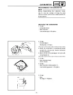
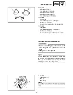
6. Check:

• needle valve 

1


• needle valve seat 

2


Damage/obstruction/wear 

 Replace the

needle valve, needle valve seat and O-ring
as a set.

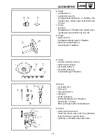
7. Check:

• O-ring 

3


Damage/wear 

 Replace the needle valve,

needle valve seat and O-ring as a set.

8. Check:

• piston valve 

1


Damage/scratches/wear 

 Replace.

• piston valve diaphragm 

2


Cracks/tears 

 Replace.

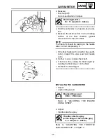
9. Check:

• vacuum chamber cover 

1


• piston valve spring 

2


• jet needle holder 

3


• jet needle spring 

4


Cracks/damage 

 Replace.

10.Check:

• jet needle kit 

1


• main jet 

2


• main jet holder 

3


• pilot jet 

4


• starter plunger 

5


Bends/damage/wear 

 Replace.

Obstruction 

 Clean.

Blow out the jets with compressed air.

11.Check:

• piston valve movement

Insert the piston valve into the carburetor
body and move it up and down.
Tightness 

 Replace the piston valve.
Summary of Contents for TW200N

Page 1: ...TW200N TW200NC SUPPLEMENTARY SERVICEMANUAL LIT 11616 14 43 2YG 28197 11 ...

Page 2: ...following manual TW200T TC 87 SERVICE MANUAL LIT 11616 05 93 2JX 28197 10 TW200EU EUC 88 SUPPLEMENTARY SERVICE MANUAL LIT 11616 06 26 2YG 28197 10 TW200N TW200NC SUPPLEMENTARY SERVICE MANUAL 2000 by Yamaha Motor Corporation U S A First edition November 2000 All rights reserved Any reproduction or unauthorized use without the written permission of Yamaha Motor Corporation U S A is expressly prohibi...

Page 3: ... to provide the customer with the most satisfaction from his vehicle and to conform to federal environmental quality objectives Yamaha Motor Company Ltd is continually striving to improve all of its models Modifications and significant changes in specifications or procedures will be forwarded to all authorized Yamaha deal ers and will appear in future editions of this manual where applicable NOTE ...

Page 4: ...of each page except in chapter 3 PERIODIC CHECKS AND ADJUSTMENTS where the sub section title s appears 3 Sub section titles appear in smaller print than the section title 4 To help identify parts and clarify procedure steps there are exploded diagrams at the start of each removal and disassembly section 5 Numbers are given in the order of the jobs in the exploded diagram A circled number indicates...

Page 5: ...ubricant B Special tool C Tightening torque D Wear limit clearance E Engine speed F Electrical data Symbols G to L in the exploded diagrams indicate the types of lubricants and lubrication points G Engine oil H Gear oil I Molybdenum disulfide oil J Wheel bearing grease K Lithium soap base grease L Molybdenum disulfide grease Symbols M to N in the exploded diagrams indicate the following M Apply lo...

Page 6: ...RT 19 ENGINE 21 ADJUSTING THE THROTTLE CABLE FREE PLAY 21 CLEANING THE SPARK ARRESTER 22 CHASSIS 23 ADJUSTING THE FRONT BRAKE 23 CHECKING THE BRAKE FLUID LEVEL 24 CHECKING THE BRAKE PADS 25 CHECKING THE BRAKE HOSE 25 BLEEDING THE HYDRAULIC BRAKE SYSTEM 26 ENGINE 28 CYLINDER HEAD 28 CHECKING THE TIMING CHAIN TENSIONER 29 INSTALLING THE TIMING CHAIN TENSIONER 29 AC MAGNETO 30 STATOR COIL ASSEMBLY AN...

Page 7: ...SASSEMBLING THE FRONT BRAKE CALIPER 57 CHECKING THE FRONT AND REAR BRAKE CALIPERS 58 ASSEMBLING AND INSTALLING THE FRONT BRAKE CALIPERS 59 FRONT FORK 62 STEERING HEAD 63 INSTALLING THE BEARING RETAINER TYPE 65 ELECTRICAL 66 ELECTRICAL COMPONENTS 66 SWITCHES 67 CHECKING SWITCH CONTINUITY 67 CHECKING THE SWITCHES 68 IGNITION SYSTEM 70 CIRCUIT DIAGRAM 70 TROUBLESHOOTING 71 ELECTRIC STARTING SYSTEM 75...

Page 8: ...0017 VEHICLE IDENTIFICATION NUMBER The vehicle identification number 1 is stamped into the right side of the steering head pipe EAS00018 MODEL CODE The model code label 1 is affixed to the frame This information will be needed to order spare parts MOTORCYCLE IDENTIFICATION ...

Page 9: ...OHC Cylinder arrangement Forward inclined single cylinder Displacement 196 cm3 11 96 cu in Bore stroke 67 0 55 7 mm 2 638 2 193 in Compression ratio 9 5 1 Compression pressure standard 900 kPa 9 kg cm2 128 psi Starting system Electric starter Carburetor Type manufacturer MV28 TEIKEI Spark plug Type manufacturer DR8EA NGK X24ESR U N D Gap 0 6 0 7 mm 0 024 0 028 in Chassis Frame type Diamond Caster ...

Page 10: ... 75 kg cm2 25 psi Off road riding 125 kPa 1 25 kg cm2 18 psi 125 kPa 1 25 kg cm2 18 psi High speed riding 150 kPa 1 5 kg cm2 22 psi 175 kPa 1 75 kg cm2 25 psi Brake Front brake type Single disc brake Operation Right hand operation Rear brake type Drum brake Operation Right foot operation Shock absorber Front shock absorber Coil spring oil damper Rear shock absorber Gas and coil spring oil damper B...

Page 11: ... 36 68 mm 1 440 1 444 in B 30 266 30 366 mm 1 192 1 196 in C 6 63 mm 0 261 in Camshaft runout limit 0 03 mm 0 0012 in Cam chain type number of links DID 25SH 104 links Cam chain adjustment method Automatic Piston ring Sectional sketch Top ring Barrel B 1 2 mm 0 047 in T 2 7 mm 0 106 in 2nd ring Taper B 1 2 mm 0 047 in T 2 7 mm 0 106 in Oil ring Expander B 2 5 mm 0 098 in T 2 8 mm 0 110 in End gap ...

Page 12: ...e M N 2 600 Pilot jet P J 31 Pilot air jet P A J TW200EN 0 95 TW200ENC 1 0 Pilot outlet 0 8 Bypass 0 7 Valve seat V S 1 6 Starter jet G S1 0 6 G S2 0 8 Fuel level above the line on the float chamber mating surface F L 0 5 1 5 mm 0 02 0 06 in Float height 10 11 mm 0 39 0 43 in Engine idling speed 1 300 1 500 r min Vacuum pressure at idling speed 29 3 34 7 kPa 220 260 mmHg 8 66 10 24 inHg or more Mo...

Page 13: ...0 1 0 7 2 Timing chain tensioner Bolt M6 2 10 1 0 7 2 Oil filter cover Bolt M6 2 10 1 0 7 2 Muffler protector Screw M6 4 7 0 7 5 1 Crankcase Bolt M6 12 10 1 0 7 2 Crankcase cover left Bolt M6 9 10 1 0 7 2 Crankcase cover right Bolt M6 12 10 1 0 7 2 Pickup coil lead holder Bolt M6 1 10 1 0 7 2 Apply LOCTITE Pickup coil Bolt M6 2 10 1 0 7 2 Apply LOCTITE Stator coil assembly Bolt M6 3 10 1 0 7 2 App...

Page 14: ...8 mm 0 03 in Master cylinder inside diameter 11 mm 0 43 in Caliper cylinder inside diameter 26 9 mm 1 06 in 22 2 mm 0 87 in Recommended fluid DOT4 Rear brake Brake type Drum brake leading and trailing Drum inside dia 110 mm 4 33 in Limit 111 mm 4 37 in Lining thickness Front 4 mm 0 16 in Limit 2 mm 0 08 in Shoe spring free length 50 5 mm 1 99 in Brake lever and brake pedal Brake lever free play at...

Page 15: ... shock absorber and frame M10 1 25 56 5 6 41 Drive chain case and swingarm M5 0 8 5 0 5 3 6 Handlebar holder upper and upper bracket M8 1 25 20 2 0 14 Steering shaft and ring nut M25 1 0 18 1 8 13 See NOTE Front brake master cylinder and handlebar M6 1 0 7 0 7 5 1 Front wheel hub and brake disc M6 1 0 13 1 3 9 4 Front brake caliper bracket and outer tube M10 1 25 30 3 0 22 Front brake caliper and ...

Page 16: ... YAMAHA Charge coil resistance color 0 5 0 7 Ω at 20 C 68 F W W Rectifier regulator Type Semi conductor type Model manufacturer SH629A 12 SHINDENGEN No load regulated voltage 14 1 14 9 V Capacity 10 A Withstand voltage 200 V Starter motor Model manufacture 5FY YAMAHA Output 0 4 kW Armature coil resistance 0 017 0 021 Ω Brush overall length 10 mm 0 39 in Limit 3 5 mm 0 14 in Brush spring pressure 5...

Page 17: ...d 7 Front turn signal position light lead left 8 Main switch lead 9 Indicator lights lead 0 Speedometer cable A Meter light lead B Headlight coupler C Wire harness D Front turn signal position light lead right E Brake hose È Fasten the brake hose with a plastic locking tie to the brake hose grommet É Fasten the wire harness with a plastic locking tie CABLE ROUTING ...

Page 18: ...protectors so that the fastener does not squeeze the hose É Pass the canister hose through the guide of the frame for California Ê Fasten the resonator hose with a plastic band in front of the resonator hose protector Ë Fasten the rectifier regulator lead and resonator hose with a plastic band between the resonator hose protectors so that the fastener does not squeeze the hose Ì Fasten the brake h...

Page 19: ...buretor overflow hose 6 AC magneto lead 7 Starter motor lead 8 Neutral switch lead È Fasten the AC magneto leads with a plastic locking tie to the frame at the section where the frame starts to curve É Fasten the carburetor air vent hose carburetor overflow hose and neutral switch lead with a plastic clip CABLE ROUTING ...

Page 20: ...itch lead and throttle cable with a plastic band É Fasten the wire harness right handlebar switch lead front brake light switch lead clutch switch lead main switch lead and resonator hose with a plastic band Ê Fasten the throttle cable and canister hose with a plastic clip Be sure to face the ends of the clip downward from the frame for California Ë Fasten the throttle cable with a plastic locking...

Page 21: ...ight switch lead clutch switch lead main switch lead resonator hose ignition coil lead ground lead and horn lead with a plastic band Í Fasten the canister hose with a plastic band for California Î Pass the canister hose through the engine stay guide for California CABLE ROUTING ...

Page 22: ...ass the rear brake light switch lead in front of the frame so that it is not squeezed by the side cover and frame Ë Fasten the rear brake light switch lead and turn signal relay lead with a plastic locking tie Ì Face the rear brake light switch lead to the rear of the frame Í Pass the battery breather hose through the hose guide Î Pass the battery breather hose through the hole in the electrical c...

Page 23: ... A Neutral switch lead B Left handlebar switch lead È Fasten the right handlebar switch lead and front brake light switch lead with a plastic band É Fasten the AC magneto leads starter motor lead neutral switch lead and battery negative lead with a plastic locking tie by pass ing the tie through the hole in the frame bracket Ê Fasten the left handlebar switch lead and clutch switch lead with a pla...

Page 24: ... left 5 Sidestand switch lead 6 Battery negative lead 7 AC magneto lead 8 Neutral switch lead 9 Starter motor lead È Fasten the wire harness and rear turn signal light lead right with a plastic locking tie at the section behind the hook É Fasten the rear turn signal light lead left with a plastic locking tie CABLE ROUTING ...

Page 25: ...km or 30 months repeat the maintenance intervals starting from 4 000 mi 6 000 km or 6 months No ITEM ROUTINE INITIAL ODOMETER READINGS 600 mi 1 000 km or 1 month 4 000 mi 6 000 km or 6 month 7 000 mi 11 000 km or 12 month 10 000 mi 16 000 km or 18 month 13 000 mi 21 000 km or 24 month 1 Valve clearance Check and adjust valve clearance when engine is cold 2 Spark plug Check condition Adjust gap and...

Page 26: ...ecessary Rear 5 Clutch Adjust free play 6 Drive chain Check chain condi tion Adjust and lubricate chain thoroughly Special O ring chain lubricant Every 300 mi 500 km 7 Control and meter cable Apply chain lube thoroughly Yamaha chain and cable lube or engine oil 8 Rear arm pivot shaft Apply until new grease shows Lithium soap based grease all purpose grease 9 Brake clutch lever pivot shaft Apply ch...

Page 27: ...r cylinder Check the brake fluid level and add fluid as required Replace the master cylinder and caliper cylinder oil seals every two years Replace the brake hoses every four years or if cracked or damaged 15 Battery Check specific gravity Check that the breather pipe is working properly Correct if neces sary 16 Sidestand switch Check and clean or replace if neces saly No ITEM ROUTINE TYPE INITIAL...

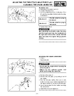
Page 28: ...the flange of the throttle grip 3 5 mm 0 12 0 20 in 2 Adjust throttle cable free play Carburetor side a Loosen the locknut 1 b Turn the adjusting nut 2 in direction a or b until the specified throttle cable free play is obtained c Tighten the locknut NOTE If the specified throttle cable free play cannot be obtained on the carburetor side of the cable use the adjusting nut on the handlebar side Dir...

Page 29: ...use the engine idling speed to change CLEANING THE SPARK ARRESTER 1 Clean Spark arrester WARNING Do not start the engine when cleaning the exhaust system Always let the exhaust system cool before performing this operation a Remove the screw 1 b Remove the tail pipe 2 by pulling it out of the muffler c Top the tail pipe lightly then use a wire brush to remove any carbon deposits from the spark arre...

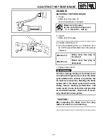
Page 30: ...en the locknut WARNING A soft or spongy feeling in the brake lever can indicate the presence of air in the brake system Before the vehicle is operated the air must be removed by bleeding the brake system Air in the brake system will consid erably reduce braking performance and could result in loss of control and possibly an accident Therefore check and if neces sary bleed the brake system CAUTION ...

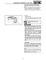
Page 31: ...ke performance Refill with the same type of brake fluid that is already in the system Mixing brake fluids may result in a harmful chemical reaction leading to poor brake performance When refilling be careful that water does not enter the brake fluid reservoir Water will significantly lower the boiling point of the brake fluid and could cause vapor lock CAUTION jC Brake fluid may damage painted sur...

Page 32: ...d Replace the brake pads as a set Refer to REPLACING THE FRONT BRAKE PADS CHECKING THE BRAKE HOSE The following procedure applies to all of the brake hose and brake hose clamps 1 Check brake hose 1 Cracks damage wear Replace 2 Check brake hose clamp Loose Tighten the clamp bolt 3 Hold the motorcycle upright and apply the brake several times 4 Check brake hose Brake fluid leakage Replace the dam ag...

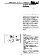
Page 33: ...ystem considerably length ening the bleeding procedure If bleeding is difficult it may be necessary to let the brake fluid settle for a few hours Repeat the bleeding procedure when the tiny bubbles in the hose have disap peared 1 Bleed hydraulic brake system a Fill the brake fluid reservoir to the proper level with the recommended brake fluid b Install the master cylinder reservoir dia phragm c Co...

Page 34: ... bubbles have disappeared from the brake fluid in the plastic hose j Tighten the bleed screw to specification k Fill the brake fluid reservoir to the proper level with the recommended brake fluid Refer to CHECKING THE BRAKE FLUID LEVEL WARNING After bleeding the hydraulic brake system check the brake operation T R Bleed screw 6 Nm 0 6 m kg 4 3 ft lb ...

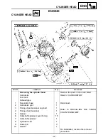
Page 35: ... CARBURETOR Fuel tank Exhaust pipe 1 Resonator hose 1 Disconnect 2 Carburetor joint 1 3 Timing chain tensioner cap bolt 1 Refer to INSTALLING THE TIMING CHAIN TENSIONER 4 Timing chain tensioner 1 5 Gasket 1 6 Camshaft sprocket cover O ring 1 1 7 Camshaft sprocket 1 8 Cylinder head 1 9 Dowel pin 3 10 Gasket 1 For installation reverse the removal procedure ...

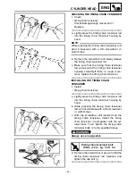
Page 36: ...t replace the timing chain tensioner INSTALLING THE TIMING CHAIN TENSIONER 1 Install timing chain tensioner a Lightly press the timing chain tensioner rod into the timing chain tensioner housing by hand b While pressing the timing chain tensioner rod wind it clockwise with a thin screwdriver 1 until it stops c With the screwdriver still inserted into the timing chain tensioner install the timing c...

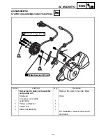
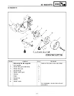
Page 37: ...10 Nm 1 0 m kg 7 2 ft Ib 4 2 3 1 Order Job Part Q ty Remarks Removing the stator coil assembly and pickup coil Remove the parts in the order listed Engine oil Drain Crankcase cover left 1 Lead holder 1 2 Pickup coil bracket 1 3 Pickup coil 1 4 Stator coil assembly 1 For installation reverse the removal procedure ...

Page 38: ...move the parts in the order listed 1 AC magneto 1 2 Starter idle gear shaft collar 1 1 3 Starter idle gear 1 4 Woodruff key 1 5 Starter wheel gear 1 6 Washer 1 7 Roller 3 8 Spring cap 3 9 Spring 3 10 Starter clutch 1 For installation reverse the removal procedure AC MAGNETO ...

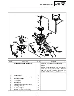
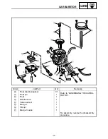
Page 39: ... Q ty Remarks Removing the carburetor Remove the parts in the order listed Seat Side cover Fuel tank 1 Throttle cable 2 2 Clamp carburetor joint 1 3 Clamp ail filter joint 1 4 Carburetor assembly 1 For installation reverse the removal procedure CARBURETOR ...

Page 40: ...disassembling the carburetor make sure to note the number of times the pilot screw is turned out from the seated position to its set position 1 Starter plunger 1 2 Vacuum chamber cover spring 1 1 3 Jet needle holder 1 4 Piston valve 1 5 Jet needle kit 1 6 Coasting enricher cover spring 1 1 7 Coasting enricher 1 8 Air vent hose joint 1 1 9 Throttle stop screw assembly 1 ...

Page 41: ...Order Job Part Q ty Remarks 0 Float chamber gasket 1 1 Refer to ASSEMBLING THE CARBU RETOR A Float pin 1 B Float 1 C Needle valve 1 D Valve seat set 1 E Main jet 1 F Pilot jet 1 G Main jet nozzle 1 For assembly reverse the disassembly procedure CARBURETOR ...

Page 42: ...G THE CARBURETOR 1 Check carburetor body float chamber Cracks damage Replace 2 Check fuel passages Obstruction Clean a Wash the carburetor in a petroleum based solvent Do not use any caustic carburetor cleaning solution b Blow out all of the passages and jets with compressed air 3 Check float chamber body Dirt Clean 4 Check float chamber rubber gasket 1 Cracks damage wear Replace 5 Check float Dam...

Page 43: ...s wear Replace piston valve diaphragm 2 Cracks tears Replace 9 Check vacuum chamber cover 1 piston valve spring 2 jet needle holder 3 jet needle spring 4 Cracks damage Replace 10 Check jet needle kit 1 main jet 2 main jet holder 3 pilot jet 4 starter plunger 5 Bends damage wear Replace Obstruction Clean Blow out the jets with compressed air 11 Check piston valve movement Insert the piston valve in...

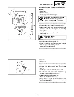
Page 44: ...place Obstruction clean Blow out to the joint with compressed air ASSEMBLING THE CARBURETOR CAUTION Before assembling the carburetors wash all of the parts in a petroleum based sol vent Always use a new gasket NOTE Before assembling the carburetor make sure to turn out the pilot screw the same number of times as noted before disassembly from the seated position to the set position 1 Install needle...

Page 45: ...he specifi cation inspect the valve seat and needle valve d If either is worn replace them both e If both are fine adjust the float height by bending the float tang 1 on the float f Recheck the float height Float height F H 10 11 mm 0 39 0 43 in INSTALLING THE CARBURETOR 1 Adjust engine idling speed Refer to ADJUSTING THE ENGINE IDLING SPEED Engine idling speed 1 350 1 550 r min 2 Adjust throttle ...

Page 46: ... level gauge vertically next to the line 4 on the float chamber f Measure the fuel level a Fuel level above the line on the float chamber mating surface 0 5 1 5 mm 0 02 0 06 in Fuel level gauge YM 01312 A 2 Adjust fuel level a Remove the carburetor assembly b Check the needle valve seat and needle valve c If either is worn replace them as a set d If both are fine adjust the float level by slightly...

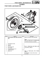
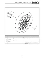
Page 47: ...rts in the order listed NOTE Place the motorcycle on a suitable stand so that the front wheel is elevated 1 Speedometer cable 1 2 Axle nut 1 Refer to REMOVING AND INSTALLING THE FRONT WHEEL 3 Washer 1 4 Front wheel axle 1 5 Front wheel 1 6 Speedometer gear unit 1 7 Collar dust seal 1 1 8 Brake disc 1 Refer to INSTALLING THE FRONT WHEEL For installation reverse the removal procedure FRONT WHEEL AND...

Page 48: ...ob Part Q ty Remarks Disassembling the front wheel Remove the parts in the order listed 1 Oil seal 1 2 Wheel bearing left and right 2 3 Spacer 1 For assembly reverse the disassembly procedure FRONT WHEEL AND BRAKE DISC ...

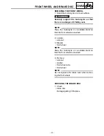
Page 49: ...NOTE Place the motorcycle on a suitable stand so that the front wheel is elevated 2 Loosen axle nut 3 Elevate front wheel NOTE Place the motorcycle on a suitable stand so that the front wheel is elevated 4 Remove axle nut washer front wheel axle front wheel NOTE Do not squeeze the brake lever when remov ing the front wheel CHECKING THE BRAKE DISC 1 Check brake disc Damage galling Replace ...

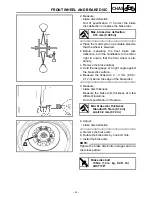
Page 50: ...ge at a right angle against the brake disc surface e Measure the deflection 2 3 mm 0 08 0 12 in below the edge of the brake disc Max brake disc deflection 0 15 mm 0 006 in 3 Measure brake disc thickness Measure the brake disc thickness at a few different locations Out of specification Replace Min brake disc thickness Standard 3 5mm 0 14 in Limit 3 0 mm 0 12 in 4 Adjust brake disc deflection a Remo...

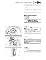
Page 51: ...ubricant Lithium soap base grease 2 Install brake discs NOTE Apply locking agent LOCTITE to the threads of the brake disc bolts Tighten the brake disc bolts in stages and in a crisscross pattern T R 13 Nm 1 3 m kg 9 4 ft lb 3 Install speedometer gear unit NOTE Make sure the projections a in the wheel hub are meshed with the slots b in the speedome ter gear unit 4 Install front wheel NOTE Make sure...

Page 52: ...ghten wheel axle nut 1 CAUTION Before tightening the wheel axle nut push down hard on the handlebars several times and check if the front fork rebounds smoothly T R 90 Nm 9 0 m kg 65 ft lb FRONT WHEEL AND BRAKE DISC ...

Page 53: ... 2 7 m kg 19 ft Ib LS 2 Order Job Part Q ty Remarks Removing the front brake pads Remove the parts in the order listed 1 Retaining bolt lower 1 2 Brake caliper 1 3 Brake pad 2 4 Brake pad spring 2 For installation reverse the removal procedure FRONT BRAKE ...

Page 54: ...y clean or new brake fluid for cleaning brake components Brake fluid may damage painted surfaces and plastic parts Therefore always clean up any spilt brake fluid immediately Avoid brake fluid coming into contact with the eyes as it can cause serious injury First aid for brake fluid entering the eyes Flush with water for 15 minutes and get immediate medical attention REPLACING THE FRONT BRAKE PADS...

Page 55: ...TE Always install new brake pads and a brake pad springs as a set a Connect a clear plastic hose 1 tightly to the bleed screw 2 Put the other end of the hose into an open container b Loosen the bleed screw and push the brake caliper pistons into the brake caliper with your finger c Tighten the bleed screw d Install new brake pad springs and a new brake pads T R Bleed screw 6 Nm 0 6 m kg 4 3 ft lb ...

Page 56: ...k brake fluid level Below the minimum level mark a Add the recommended brake fluid to the proper level Refer to CHECKING THE BRAKE FLUID LEVEL 7 Check brake lever operation Soft or spongy feeling Bleed the brake system Refer to BLEEDING THE HYDRAULIC BRAKE SYSTEM FRONT BRAKE ...

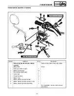
Page 57: ...rake master cylinder Remove the parts in the order listed Brake fluid Drain 1 Rear view mirror right 1 2 Brake lever spring 1 1 3 Front brake light switch 1 4 Union bolt 1 5 Copper washer 2 6 Brake hose 1 7 Brake master cylinder holder 1 8 Brake master cylinder reservoir cap 1 9 Brake master cylinder assembly 1 For installation reverse the removal procedure FRONT BRAKE ...

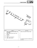
Page 58: ...ling the front brake mas ter cylinder Remove the parts in the order listed 1 Brake master cylinder reservoir dia phragm 1 2 Dust boot 1 3 Circlip 1 4 Brake master cylinder kit 1 5 Brake master cylinder 1 For assembly reverse the disassembly procedure FRONT BRAKE ...

Page 59: ...id place a container under the master cylinder and the end of the brake hose 2 3 2 1 CHECKING THE FRONT BRAKE MASTER CYLINDER 1 Check brake master cylinder 1 Damage scratches wear Replace brake fluid delivery passages brake master cylinder body Obstruction Blow out with compressed air 1 2 Check brake master cylinder kit Damage scratches wear Replace 3 Check brake master cylinder reservoir 1 Cracks...

Page 60: ...holder with the punch mark a in the right handlebar First tighten the upper bolt then the lower bolt Recommended brake fluid DOT 4 T R 7 Nm 0 4 m kg 5 1 ft lb 2 Install copper washers brake hose union bolt WARNING Proper brake hose routing is essential to insure safe motorcycle operation Refer to CABLE ROUTING NOTE While holding the brake hose tighten the union bolt as shown Turn the handlebars to...

Page 61: ...ater does not enter the brake fluid reservoir Water will significantly lower the boiling point of the brake fluid and could cause vapor lock CAUTION Brake fluid may damage painted surfaces and plastic parts Therefore always clean up any spilt brake fluid immediately 4 Bleed brake system Refer to BLEEDING THE HYDRAULIC BRAKE SYSTEM Recommended brake fluid DOT 4 5 Check brake fluid level Below the m...

Page 62: ...b T R 27 Nm 2 7 m kg 19 ft Ib LS Order Job Part Q ty Remarks Removing the front brake calipers Remove the parts in the order listed Brake fluid Drain 1 Union bolt 1 2 Copper washer 2 3 Brake hose 1 4 Retaining bolt 2 Loosen 5 Brake caliper 1 For installation reverse the removal procedure FRONT BRAKE ...

Page 63: ...brake cali pers Remove the parts in the order listed 1 Retaining bolt 2 2 Brake caliper bracket 1 3 Brake pad 2 4 Brake pad spring 2 5 Brake caliper piston 2 6 Brake caliper piston seal 4 7 Bleed screw 1 For assembly reverse the disassembly procedure FRONT BRAKE ...

Page 64: ...r and pump out the brake fluid carefully 2 1 3 2 Remove brake caliper pistons 1 brake caliper piston seals 2 a Blow compressed air into the brake hose joint opening a to force out the pistons from the brake caliper WARNING Cover the brake caliper pistons with a rag Be careful not to get injured when the pistons are expelled from the brake cali per Never try to pry out the brake caliper pis tons b ...

Page 65: ...ssem bled 1 Check brake caliper pistons 1 Rust scratches wear Replace the brake caliper brake caliper cylinders 2 Scratches wear Replace the brake cali per brake calipers Cracks damage Replace brake fluid delivery passages brake caliper body Obstruction Blow out with compressed air WARNING Whenever a brake caliper is disassembled replace the brake caliper piston seals 2 1 2 2 Check brake caliper b...

Page 66: ...ce the brake caliper piston seals Recommended brake fluid DOT 4 1 Install brake caliper bracket 1 brake caliper 2 NOTE Temporarily tighten the retaining bolts 2 1 T R 30 Nm 3 0 m kg 22 ft lb 2 Install copper washers brake hose 1 union bolt 2 WARNING Proper brake hose routing is essential to insure safe motorcycle operation Refer to CABLE ROUTING CAUTION When installing the brake hose onto the brak...

Page 67: ...ith the same type of brake fluid that is already in the system Mixing brake fluids may result in a harmful chemical reaction leading to poor brake performance When refilling be careful that water does not enter the brake fluid reservoir Water will significantly lower the boiling point of the brake fluid and could cause vapor lock CAUTION Brake fluid may damage painted surfaces and plastic parts Th...

Page 68: ... minimum level mark a Add the recommended brake fluid to the proper level Refer to CHECKING THE BRAKE FLUID LEVEL 8 Check brake lever operation Soft or spongy feeling Bleed the brake system Refer to BLEEDING THE HYDRAULIC BRAKE SYSTEM FRONT BRAKE ...

Page 69: ...e front fork legs Remove the parts in the order listed The following procedure applies to both of the front fork legs Front wheel Refer to FRONT WHEEL AND BRAKE DISCS 1 Brake hose holder 1 2 Cable guide 1 3 Front fender 1 4 Upper bracket pinch bolt 1 Loosen 5 Cap bolt 1 Loosen 6 Lower bracket pinch bolt 2 Loosen 7 Front fork leg 1 For installation reverse the removal procedure FRONT FORK ...

Page 70: ...y Remarks Removing the lower bracket Remove the parts in the order listed Front fork legs Headlight stay assembly meter assem bly 1 Main switch coupler 1 Disconnect 2 Steering stem bolt 1 3 Upper bracket 1 4 Ring nut 1 5 Lower bracket 1 6 Bearing cover 1 7 Bearing inner race 1 8 Upper bearing 1 9 Lower bearing 1 10 Bearing inner race 1 11 Rubber washer 1 STEERING HEAD ...

Page 71: ...ft lb 2nd 18 Nm 1 8 m kg 13 ft lb T R 90 Nm 9 0 m kg 65 ft Ib LS LS LS 9 10 11 5 13 12 4 6 7 8 3 2 1 Order Job Part Q ty Remarks 12 Bearing outer race 1 13 Bearing outer rase 1 For installation reverse the removal procedure STEERING HEAD ...

Page 72: ...nstall the bearing retainer type make sure that the projections 1 on the surface of the bearing face upward Since there are differences in both the upper and lower bearings the bearings can be identified by the projection on the surface of the retainer È Upper É Lower 1 È 1 É STEERING HEAD ...

Page 73: ...light switch 4 Main fuse 5 Starter relay 6 Neutral relay 7 Diode 8 CDI unit 9 Clutch switch 0 Battery A Rectifier regulator B Turn signal relay C Sidestand switch D Neutral switch E Pickup coil F Stator coil assembly G Rear brake light switch H Horn I Ignition coil ELECTRICAL COMPONENTS ...

Page 74: ...uity switch back and forth between the switch positions a few times The terminal connections for switches e g main switch engine stop switch are shown in an illustration similar to the one on the left The switch positions a are shown in the far left column and the switch lead colors b are shown in the top row in the switch illustration NOTE indicates a continuity of electricity between switch term...

Page 75: ...TY Damage wear Repair or replace the switch Improperly connected Properly connect Incorrect continuity reading Replace the switch A Sb B B B BLUE 9 0 B B 8 B B BLACK 6 OFF ON 7 OFF RUN L W R W R W B L W R W R W B 5 B B 4 R R Br L Br L L B L B L Y L Y OFF ON RED L NL OFF NR R 1 2 3 LO HI FREE PUSH Br W Ch Dg P G Br Y B Y Br W Ch B Dg L B P BLACK CHECKING THE SWITCHES ...

Page 76: ...h 2 Turn signal switch 3 Dimmer switch 4 Main switch 5 Clutch switch 6 Start switch 7 Engine stop switch 8 Front brake light switch 9 Rear brake light switch 0 Fuse A Neutral switch B Sidestand switch CHECKING THE SWITCHES ...

Page 77: ...Y L B R Br L Y B B L B L W R W R W B W B B O O B L Y B B B L Y L Y L B L W L B L B N O S T U V Br P P L B B W B B B W G Y G Y Br R OFF ON LO HI FREE PUSH RED RED L W L B L B L W Br B W Br W Sb L W BLUE BLUE B B G Y Br BLACK BLACK F G H I O B W L W R B R G W L Y Br Sb B Br W Br B Dg Br Sb Ch Br W Ch B Dg L B B Br Br W P P Ch Dg B B B B B B Y Y Y G G Ch L Ch Ch Br W Br W Br Br Dg P Q B Dg Q R R G B ...

Page 78: ...ght Troubleshoot with the following special tool s YES NO The ignition system fails to operate no spark or intermittent spark Dynamic spark tester YM 34487 Pocket tester YU 03112 1 Spark plug The following procedure applies to all of the spark plug Check the condition of the spark plug Check the spark plug type Measure the spark plug gap Standard spark plug DR8EA NGK X24ESR U DENSO Spark plug gap ...

Page 79: ...dually increase the spark gap until a misfire occurs Min ignition spark gap 6 mm 0 24 in Is there a spark and is the spark gap within specification The ignition system is OK 3 Spark plug cap resistance The following procedure applies to all of the spark plug cap Disconnect the spark plug cap from the spark plug Connect the pocket tester Ω 1k to the spark plug cap as shown Measure the spark plug ca...

Page 80: ...wn Measure the secondary coil resistance Tester positive probe orange Tester positive probe spark plug lead Secondary coil resistance 6 32 9 48 kΩ at 20 C 68 F Is the ignition coil OK Replace the ignition coil 5 Pickup coil resistance Disconnect the pickup coil coupler from the wire harness Connect the pocket tester Ω 100 to the pickup coil terminal as shown Tester positive probe white 1 Tester ne...

Page 81: ...the main switch for continuity Refer to CHECKING THE SWITCHES Is the main switch OK Replace the main switch 8 Engine stop switch Check the engine stop switch for continuity Refer to CHECKING THE SWITCHES Is the engine stop switch OK Replace the right handlebar switch 9 Sidestand switch Check the sidestand switch for continuity Refer to CHECKING THE SWITCHES Is the sidestand switch OK Replace the s...

Page 82: ... W B B O O B L Y B B B L Y L Y L B L W L B L B N O S T U V Br P P L B B W B B B W G Y G Y Br R OFF ON LO HI FREE PUSH RED RED L W L B L B L W Br B W Br W Sb L W BLUE BLUE B B G Y Br BLACK BLACK F G H I O B W L W R B R G W L Y Br Sb B Br W Br B Dg Br Sb Ch Br W Ch B Dg L B B Br Br W P P Ch Dg B B B B B B Y Y Y G G Ch L Ch Ch Br W Br W Br Br Dg P Q B Dg Q R R G B Y Dg X Br W Br BLACK BLACK BLACK W 2...

Page 83: ... neutral switch is closed The clutch lever is pulled to the handlebar the clutch switch is closed and the side stand is up the sidestand switch is closed WHEN THE TRANSMISSION IS IN NEUTRAL WHEN THE SIDESTAND IS UP AND THE CLUTCH LEVER IS PULLED TO THE HANDLEBAR 1 Starter motor 2 Battery 3 Starter relay 4 Main fuse 5 Main switch 6 Start switch 7 Diode 8 Clutch switch 9 Sidestand switch 0 Neutral r...

Page 84: ...ck the main fuse for continuity Are the main fuse OK Replace the fuse 2 Battery Check the battery fluid level battery termi nal and specific gravity Specific gravity 1 280 at 20 C 68 F Is the battery OK Refill battery fluid Clean the battery terminals Recharge or replace the battery 3 Starter motor Connect the battery positive terminal 1 and starter motor lead 2 with a jumper lead 3 WARNING A wire...

Page 85: ...hite 3 Tester negative probe black white 4 Does the neutral relay have continuity between blue white and black white Replace the Neutral relay 5 Diode Remove the diode from the wire harness Connect the pocket tester Ω 1 to the diode terminals as shown Check the diode for continuity Tester positive probe blue white 1 Tester negative probe blue black 2 Continu ity Tester positive probe blue black 2 ...

Page 86: ...he main switch for continuity Refer to CHECKING THE SWITCHES Is the main switch OK Replace the main switch 8 Engine stop switch Check the engine stop switch for continuity Refer to CHECKING THE SWITCHES Is the engine stop switch OK Replace the right handlebar switch 9 Neutral switch Check the neutral switch for continuity Refer to CHECKING THE SWITCHES Is the neutral switch OK Replace the neutral ...

Page 87: ...s the start switch OK Replace the right handlebar switch 13 Wiring Check the entire starting system s wiring Refer to CIRCUIT DIAGRAM Is the starting system s wiring properly con nected and without defects Properly connect or repair the starting system s wiring The starting system circuit is OK ELECTRIC STARTING SYSTEM ...

Page 88: ...P P L B B W B B B W G Y G Y Br R OFF ON LO HI FREE PUSH RED RED L W L B L B L W Br B W Br W Sb L W BLUE BLUE B B G Y Br BLACK BLACK F G H I O B W L W R B R G W L Y Br Sb B Br W Br B Dg Br Sb Ch Br W Ch B Dg L B B Br Br W P P Ch Dg B B B B B B Y Y Y G G Ch L Ch Ch Br W Br W Br Br Dg P Q B Dg Q R R G B Y Dg X Br W Br BLACK BLACK BLACK W 2 Neutral switch 4 Battery 5 Main fuse A Main switch J Neutral ...

Page 89: ...inuity Are the main system fuse OK Replace the fuse 2 Battery Check the battery fluid level battery termi nal and specific gravity Specific gravity 1 280 at 20 C 68 F Is the battery OK Refill battery fluid Clean the battery terminals Recharge or replace the battery 3 Main switch Check the main switch for continuity Refer to CHECKING THE SWITCHES Is the main switch OK Replace the main switch 4 Wiri...

Page 90: ...rminal Is the voltage within specification The wiring circuit from the main switch to the horn connec tors is faulty and must be repaired 3 Horn Disconnect the pink connector at the horn terminal Connect a jumper lead 1 to the horn termi nal and ground the jumper lead Set the main switch to ON Push the horn switch Does the horn sound The horn is OK 4 Voltage Connect the pocket tester DC 20 V to th...

Page 91: ...ltage Connect the pocket tester DC 20 V to the tail brake light connectors wire harness side as shown Tester positive probe yellow 1 Tester negative probe black 2 Set the main switch to ON Pull in the brake lever or push down on the brake pedal Measure the voltage 12 V of yellow at the tail brake light connector wire harness side Is the voltage within specification This circuit is OK The wiring ci...

Page 92: ...ES Is the turn signal switch OK Replace the left han dlebar switch 4 Voltage Connect the pocket tester DC 20 V to the turn signal relay coupler wire harness side as shown Tester positive probe brown 1 Tester negative probe ground Set the main switch to ON Measure the voltage 12 V of brown 1 at the turn signal relay coupler wire harness side Is the voltage within specification The wiring circuit fr...

Page 93: ... the meter assembly coupler wire harness side as shown È Turn signal light É Turn signal indicator light Left turn signal light Tester positive probe chocolate 1 Tester negative probe ground Right turn signal light Tester positive probe dark green 2 Tester negative probe ground Turn indicator light Tester positive probe brown 3 Tester negative probe ground Set the main witch to ON Set the turn sig...

Page 94: ...r to CHECKING THE SWITCHES Is the neutral switch OK Replace the neutral switch 3 Voltage Connect the pocket tester DC 20 V to the meter assembly coupler wire harness side as shown Tester positive probe brown 1 Tester negative probe sky blue 2 Set the main switch to ON Measure the voltage 12 V of brown 1 and sky blue 2 at the meter assembly coupler Is the voltage within specification This circuit i...

Page 95: ...YAMAHA MOTOR CO LTD 2500 SHINGAI IWATA SHIZUOKA JAPAN PRINTED IN U S A ...

Page 96: ...R G W W L W R L Y 1 2 4 5 8 9 A B C D E 6 Sb Sb Br K Br Br Br L R W Br Sb Sb 3 R B B B B B R R R R W W W R R W B L W L W B B B R W R Br L W Sb B W Br BLACK R 7 OFF ON 0 OFF RUN B W B R W L W L W R W R W B R Br L L B L Y L B R Br L Y B B L B L W R W R W B W B B O O B L Y B B B L Y L Y L B L W L B L B N O S T U V Br P P L B B W B B B W G Y G Y Br R OFF ON LO HI FREE PUSH RED RED L W L B L B L W Br B...

Reviews: