INSP
ADJ
2-87
Control rod
RS90GTZ/RS90LTGTZ
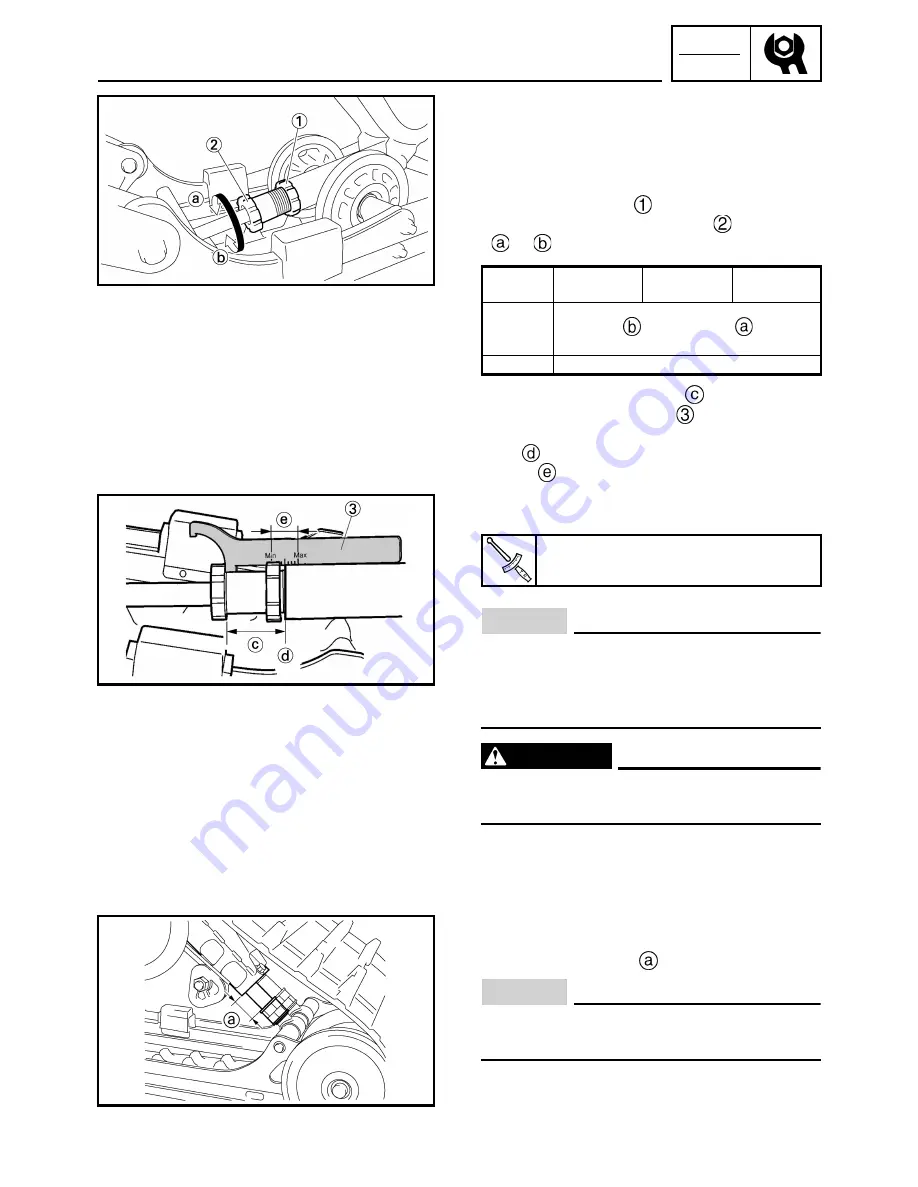
1. Adjust:
• Control rod stroke
Adjustment steps:
• Loosen the locknut
.
• Turn the control rod adjuster
in direction
or
to adjust the control rod stroke.
• Check the adjuster length
using the scale
on the special wrench
included in the
owner’s tool kit as shown. Make sure that the
rim
of the control rod body is within the
range
of the scale.
• While holding the adjuster securely, tighten
the locknut.
NOTICE
When using the special wrench, make sure
that it is situated at a right angle to the con-
trol rod, and that it is tightly fitted to the
locknut or the control rod adjuster.
WARNING
Never adjust the control rod beyond the
range of the scale on the special wrench.
RST90GTZ
1. Adjust:
• Control rod stroke
NOTICE
Make sure the adjusting nut ends are set at
the same position on each side.
Adjusting
position
MIN
STD
MAX
Effect
Decrease
Pitching
←
→
Increase
weight
transfer
Standard
Fourth mark to the left of MAX
Control rod adjusting locknut:
35 Nm (3.5 m•kgf, 25 ft•lbf)
REAR SUSPENSION
Summary of Contents for Vector RS90GTZ
Page 1: ......
Page 74: ...INSP ADJ 2 51 Rear RST90GTZ Nipple Nipple both sides LUBRICATION ...
Page 329: ...FI 7 2 Passenger grip warmer relay RS90GTZ RS90LTGTZ RST90GTZ FUEL INJECTION SYSTEM ...
Page 330: ...FI 7 3 CIRCUIT DIAGRAM RS90GTZ RS90LTGTZ FUEL INJECTION SYSTEM ...
Page 332: ...FI 7 5 CIRCUIT DIAGRAM RST90GTZ FUEL INJECTION SYSTEM ...
Page 368: ...ELEC 8 2 IGNITION SYSTEM CIRCUIT DIAGRAM RS90GTZ RS90LTGTZ IGNITION SYSTEM ...
Page 370: ...ELEC 8 4 CIRCUIT DIAGRAM RST90GTZ IGNITION SYSTEM ...
Page 393: ...ELEC 8 27 CHARGING SYSTEM ...
Page 394: ...ELEC 8 28 LIGHTING SYSTEM CIRCUIT DIAGRAM RS90GTZ RS90LTGTZ LIGHTING SYSTEM ...
Page 396: ...ELEC 8 30 CIRCUIT DIAGRAM RST90GTZ LIGHTING SYSTEM ...
Page 404: ...ELEC 8 38 SIGNAL SYSTEM CIRCUIT DIAGRAM RS90GTZ RS90LTGTZ SIGNAL SYSTEM ...
Page 406: ...ELEC 8 40 CIRCUIT DIAGRAM RST90GTZ SIGNAL SYSTEM ...
Page 419: ...ELEC 8 53 SIGNAL SYSTEM ...
Page 420: ...ELEC 8 54 GRIP WARMER SYSTEM CIRCUIT DIAGRAM RS90GTZ RS90LTGTZ GRIP WARMER SYSTEM ...
Page 422: ...ELEC 8 56 CIRCUIT DIAGRAM RST90GTZ GRIP WARMER SYSTEM ...
Page 430: ...ELEC 8 64 COOLING SYSTEM CIRCUIT DIAGRAM RS90GTZ RS90LTGTZ COOLING SYSTEM ...
Page 458: ...SPEC 9 25 CABLE ROUTING CABLE ROUTING ...
Page 460: ...SPEC 9 27 CABLE ROUTING ...
Page 462: ...SPEC 9 29 RS90GTZ RS90LTGTZ CABLE ROUTING ...
Page 464: ...SPEC 9 31 RS90GTZ RS90LTGTZ CABLE ROUTING ...
Page 466: ...SPEC 9 33 RST90GTZ CABLE ROUTING ...
Page 468: ...SPEC 9 35 RST90GTZ CABLE ROUTING ...
Page 470: ...SPEC 9 37 RST90GTZ CABLE ROUTING ...
Page 472: ...SPEC 9 39 RS90GTZ RS90LTGTZ CABLE ROUTING ...
Page 474: ...SPEC 9 41 RS90GTZ RS90LTGTZ CABLE ROUTING ...
Page 476: ...SPEC 9 43 RST90GTZ CABLE ROUTING ...
Page 478: ...SPEC 9 45 RST90GTZ CABLE ROUTING ...
Page 480: ...SPEC 9 47 CABLE ROUTING ...
Page 482: ...SPEC 9 49 CABLE ROUTING ...
Page 484: ...SPEC 9 51 RS90GTZ RS90LTGTZ CABLE ROUTING ...
Page 486: ...SPEC 9 53 RST90GTZ CABLE ROUTING ...
Page 488: ...SPEC 9 55 RS90GTZ RS90LTGTZ CABLE ROUTING ...
Page 490: ...SPEC 9 57 RST90GTZ CABLE ROUTING ...
Page 492: ...SPEC 9 59 RST90GTZ CABLE ROUTING ...
Page 498: ......
Page 499: ......
Page 500: ......
Page 501: ...WIRING DIAGRAM 2010 RS90GTZ RS90LTGTZ 8JA 0F001 00 ...
Page 502: ...WIRING DIAGRAM 2010 RST90GTZ 8HF 0F001 00 ...
Page 503: ...WIRING DIAGRAM 2010 RS90GTZ RS90LTGTZ 8JA 0F001 00 ...


