ENG
5-46
4. Inspect:
• Starter clutch operation
Installation steps:
• Install the starter clutch gear onto the starter
clutch and hold the AC magneto rotor.
• When turning the starter clutch gear clock-
wise
, it should turn freely, otherwise the
starter clutch is faulty and must be replaced.
• When turning the starter clutch gear counter-
clockwise
, the starter clutch and the
starter clutch gear should engage, otherwise
the starter clutch is faulty and must be
replaced.
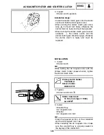
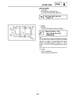
INSTALLATION
1. Install:
• Starter clutch
TIP
While holding the AC magneto rotor with the
primary clutch holder (sheave holder), tighten
the starter clutch bolts.
2. Tighten:
• Starter clutch bolts
3. Install:
• Woodruff key
• AC magneto rotor
• Washer
• AC magneto rotor bolt
TIP
• Clean the tapered portion of the crankshaft
and the AC magneto rotor hub.
• When installing the AC magneto rotor, make
sure the woodruff key is properly seated in
the keyway of the crankshaft.
Primary clutch holder:
YS-01880-A
Sheave holder:
90890-01701
Starter clutch bolt:
16 Nm (1.6 m•kgf, 11 ft•lbf)
LOCTITE
®
AC MAGNETO ROTOR AND STARTER CLUTCH
Summary of Contents for Vector RS90GTZ
Page 1: ......
Page 74: ...INSP ADJ 2 51 Rear RST90GTZ Nipple Nipple both sides LUBRICATION ...
Page 329: ...FI 7 2 Passenger grip warmer relay RS90GTZ RS90LTGTZ RST90GTZ FUEL INJECTION SYSTEM ...
Page 330: ...FI 7 3 CIRCUIT DIAGRAM RS90GTZ RS90LTGTZ FUEL INJECTION SYSTEM ...
Page 332: ...FI 7 5 CIRCUIT DIAGRAM RST90GTZ FUEL INJECTION SYSTEM ...
Page 368: ...ELEC 8 2 IGNITION SYSTEM CIRCUIT DIAGRAM RS90GTZ RS90LTGTZ IGNITION SYSTEM ...
Page 370: ...ELEC 8 4 CIRCUIT DIAGRAM RST90GTZ IGNITION SYSTEM ...
Page 393: ...ELEC 8 27 CHARGING SYSTEM ...
Page 394: ...ELEC 8 28 LIGHTING SYSTEM CIRCUIT DIAGRAM RS90GTZ RS90LTGTZ LIGHTING SYSTEM ...
Page 396: ...ELEC 8 30 CIRCUIT DIAGRAM RST90GTZ LIGHTING SYSTEM ...
Page 404: ...ELEC 8 38 SIGNAL SYSTEM CIRCUIT DIAGRAM RS90GTZ RS90LTGTZ SIGNAL SYSTEM ...
Page 406: ...ELEC 8 40 CIRCUIT DIAGRAM RST90GTZ SIGNAL SYSTEM ...
Page 419: ...ELEC 8 53 SIGNAL SYSTEM ...
Page 420: ...ELEC 8 54 GRIP WARMER SYSTEM CIRCUIT DIAGRAM RS90GTZ RS90LTGTZ GRIP WARMER SYSTEM ...
Page 422: ...ELEC 8 56 CIRCUIT DIAGRAM RST90GTZ GRIP WARMER SYSTEM ...
Page 430: ...ELEC 8 64 COOLING SYSTEM CIRCUIT DIAGRAM RS90GTZ RS90LTGTZ COOLING SYSTEM ...
Page 458: ...SPEC 9 25 CABLE ROUTING CABLE ROUTING ...
Page 460: ...SPEC 9 27 CABLE ROUTING ...
Page 462: ...SPEC 9 29 RS90GTZ RS90LTGTZ CABLE ROUTING ...
Page 464: ...SPEC 9 31 RS90GTZ RS90LTGTZ CABLE ROUTING ...
Page 466: ...SPEC 9 33 RST90GTZ CABLE ROUTING ...
Page 468: ...SPEC 9 35 RST90GTZ CABLE ROUTING ...
Page 470: ...SPEC 9 37 RST90GTZ CABLE ROUTING ...
Page 472: ...SPEC 9 39 RS90GTZ RS90LTGTZ CABLE ROUTING ...
Page 474: ...SPEC 9 41 RS90GTZ RS90LTGTZ CABLE ROUTING ...
Page 476: ...SPEC 9 43 RST90GTZ CABLE ROUTING ...
Page 478: ...SPEC 9 45 RST90GTZ CABLE ROUTING ...
Page 480: ...SPEC 9 47 CABLE ROUTING ...
Page 482: ...SPEC 9 49 CABLE ROUTING ...
Page 484: ...SPEC 9 51 RS90GTZ RS90LTGTZ CABLE ROUTING ...
Page 486: ...SPEC 9 53 RST90GTZ CABLE ROUTING ...
Page 488: ...SPEC 9 55 RS90GTZ RS90LTGTZ CABLE ROUTING ...
Page 490: ...SPEC 9 57 RST90GTZ CABLE ROUTING ...
Page 492: ...SPEC 9 59 RST90GTZ CABLE ROUTING ...
Page 498: ......
Page 499: ......
Page 500: ......
Page 501: ...WIRING DIAGRAM 2010 RS90GTZ RS90LTGTZ 8JA 0F001 00 ...
Page 502: ...WIRING DIAGRAM 2010 RST90GTZ 8HF 0F001 00 ...
Page 503: ...WIRING DIAGRAM 2010 RS90GTZ RS90LTGTZ 8JA 0F001 00 ...

