FI
7-13
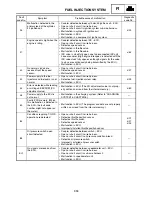
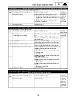
Fault
code No.
Symptom
Probable cause of malfunction
Diagnostic
code No.
35
Malfunction detected in the
primary lead of the cylinder-
#3 ignition coil.
• Coupler defective between cylinder-#3 ignition coil – ECU.
• Open or short circuit in wire harness.
• Open or short circuit in ignition system sub-wire harness.
• Malfunction in cylinder-#3 ignition coil.
• Malfunction in ECU.
• Malfunction in a component of ignition system.
d:32
37
Engine speed is high when the
engine is idling.
• Coupler defective between ISC – ECU.
• Open or short circuit in wire harness.
• Defective speed sensor.
• Malfunction in throttle valve.
• Malfunction in throttle cable.
• ISC valve is stuck fully open due to disconnected ISC unit
hose or coupler. (High engine idle speed is detected with the
ISC valve stuck fully open even though signals for the valve
to close are continuously being transmitted by the ECU.)
• Malfunction in ECU.
d:54
42
No normal signals are
received from the speed
sensor.
• Open or short circuit in wire harness.
• Defective speed sensor.
• Malfunction in ECU.
d:07
43
Power supply to the fuel
injectors and fuel pump is not
normal.
• Open or short circuit in wire harness.
• Defective fuel injection system relay.
• Malfunction in ECU.
d:09
44
Error is detected while reading
or writing on EEPROM (CO
adjustment value).
• Malfunction in ECU. (The CO adjustment value is not prop-
erly written on or read from the internal memory.)
d:60
46
Power supply to the ECU is
not normal.
• Malfunction in the charging system. (Refer to “CHARGING
SYSTEM” in CHAPTER 8.)
—
50
Faulty ECU memory. (When
this malfunction is detected in
the ECU, the fault code
number might not appear on
the meter.)
• Malfunction in ECU. (The program and data are not properly
written on or read from the internal memory.)
—
84
Conditions requiring T.O.R.S.
operation are detected.
• Open or short circuit in wire harness.
• Defective throttle position sensor.
• Defective throttle switch.
• Defective speed sensor.
• Malfunction in ECU.
• Improperly installed throttle position sensor.
d:01
d:07
d:24
85
Oil pressure switch: open
circuit detected.
• Coupler defective between switch – ECU.
• Open or short circuit in wire harness.
• Open or short circuit in oil pressure switch sub-lead.
• Defective oil pressure switch.
• Improperly installed oil pressure switch.
• Malfunction in ECU.
—
Er-1
No signals are received from
the ECU.
• Coupler defective between speedometer unit – ECU.
• Open or short circuit in wire harness.
• Open or short circuit in sub-wire harness 2.
• Malfunction in speedometer unit.
• Malfunction in ECU.
—
FUEL INJECTION SYSTEM
Summary of Contents for Vector RS90GTZ
Page 1: ......
Page 74: ...INSP ADJ 2 51 Rear RST90GTZ Nipple Nipple both sides LUBRICATION ...
Page 329: ...FI 7 2 Passenger grip warmer relay RS90GTZ RS90LTGTZ RST90GTZ FUEL INJECTION SYSTEM ...
Page 330: ...FI 7 3 CIRCUIT DIAGRAM RS90GTZ RS90LTGTZ FUEL INJECTION SYSTEM ...
Page 332: ...FI 7 5 CIRCUIT DIAGRAM RST90GTZ FUEL INJECTION SYSTEM ...
Page 368: ...ELEC 8 2 IGNITION SYSTEM CIRCUIT DIAGRAM RS90GTZ RS90LTGTZ IGNITION SYSTEM ...
Page 370: ...ELEC 8 4 CIRCUIT DIAGRAM RST90GTZ IGNITION SYSTEM ...
Page 393: ...ELEC 8 27 CHARGING SYSTEM ...
Page 394: ...ELEC 8 28 LIGHTING SYSTEM CIRCUIT DIAGRAM RS90GTZ RS90LTGTZ LIGHTING SYSTEM ...
Page 396: ...ELEC 8 30 CIRCUIT DIAGRAM RST90GTZ LIGHTING SYSTEM ...
Page 404: ...ELEC 8 38 SIGNAL SYSTEM CIRCUIT DIAGRAM RS90GTZ RS90LTGTZ SIGNAL SYSTEM ...
Page 406: ...ELEC 8 40 CIRCUIT DIAGRAM RST90GTZ SIGNAL SYSTEM ...
Page 419: ...ELEC 8 53 SIGNAL SYSTEM ...
Page 420: ...ELEC 8 54 GRIP WARMER SYSTEM CIRCUIT DIAGRAM RS90GTZ RS90LTGTZ GRIP WARMER SYSTEM ...
Page 422: ...ELEC 8 56 CIRCUIT DIAGRAM RST90GTZ GRIP WARMER SYSTEM ...
Page 430: ...ELEC 8 64 COOLING SYSTEM CIRCUIT DIAGRAM RS90GTZ RS90LTGTZ COOLING SYSTEM ...
Page 458: ...SPEC 9 25 CABLE ROUTING CABLE ROUTING ...
Page 460: ...SPEC 9 27 CABLE ROUTING ...
Page 462: ...SPEC 9 29 RS90GTZ RS90LTGTZ CABLE ROUTING ...
Page 464: ...SPEC 9 31 RS90GTZ RS90LTGTZ CABLE ROUTING ...
Page 466: ...SPEC 9 33 RST90GTZ CABLE ROUTING ...
Page 468: ...SPEC 9 35 RST90GTZ CABLE ROUTING ...
Page 470: ...SPEC 9 37 RST90GTZ CABLE ROUTING ...
Page 472: ...SPEC 9 39 RS90GTZ RS90LTGTZ CABLE ROUTING ...
Page 474: ...SPEC 9 41 RS90GTZ RS90LTGTZ CABLE ROUTING ...
Page 476: ...SPEC 9 43 RST90GTZ CABLE ROUTING ...
Page 478: ...SPEC 9 45 RST90GTZ CABLE ROUTING ...
Page 480: ...SPEC 9 47 CABLE ROUTING ...
Page 482: ...SPEC 9 49 CABLE ROUTING ...
Page 484: ...SPEC 9 51 RS90GTZ RS90LTGTZ CABLE ROUTING ...
Page 486: ...SPEC 9 53 RST90GTZ CABLE ROUTING ...
Page 488: ...SPEC 9 55 RS90GTZ RS90LTGTZ CABLE ROUTING ...
Page 490: ...SPEC 9 57 RST90GTZ CABLE ROUTING ...
Page 492: ...SPEC 9 59 RST90GTZ CABLE ROUTING ...
Page 498: ......
Page 499: ......
Page 500: ......
Page 501: ...WIRING DIAGRAM 2010 RS90GTZ RS90LTGTZ 8JA 0F001 00 ...
Page 502: ...WIRING DIAGRAM 2010 RST90GTZ 8HF 0F001 00 ...
Page 503: ...WIRING DIAGRAM 2010 RS90GTZ RS90LTGTZ 8JA 0F001 00 ...


