FI
7-24
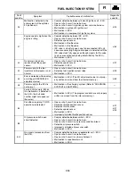
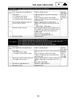
Fault code No.
26
Symptom
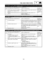
Intake air pressure sensor 2 (cylinder #1): hose system malfunction (clogged or
detached hose).
Diagnostic code No. d:04 (intake air pressure sensor 2 (cylinder #1))
Order
Item/components and probable cause
Check or maintenance job
Reinstate-
ment method
1
Intake air pressure sensor 2 (cylinder #1)
hose is detached, clogged, kinked, or
pinched.
Repair or replace the intake air pressure sensor 2
(cylinder #1) hose.
Starting the
engine and
operating it at
idle.
2
Defective intake air pressure sensor 2 (cyl-
inder #1).
Execute the diagnostic mode (code No. d:04).
Replace if defective.
Refer to “Fault code No. 25”.
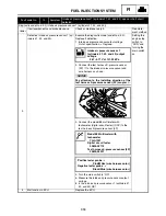
Fault code No.
30
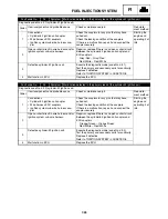
Symptom Engine stops when an oil pressure drop is detected.
Diagnostic code No. – –
Order
Item/components and probable cause
Check or maintenance job
Reinstate-
ment method
1
Oil pressure dropped.
Place the snowmobile on a level surface, and then
check the oil pressure after warming up the engine.
Refer to “ENGINE OIL REPLACEMENT” in CHAP-
TER 2.
Setting the
engine stop
switch to
“RUN” and
turning the
main switch
ON
→
OFF
→
ON.
2
Defective oil pressure switch.
Start the engine, warm it up for 1 minute, and then
use the circuit tester to check for continuity between
the oil pressure switch coupler (yellow/green) and
the switch body.
Replace if there is continuity.
3
Malfunction in ECU.
Replace the ECU.
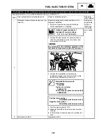
Fault code No.
33
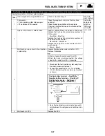
Symptom Malfunction detected in the primary lead of the cylinder-#1 ignition coil.
Diagnostic code No. d:30 (cylinder-#1 ignition coil)
Order
Item/components and probable cause
Check or maintenance job
Reinstate-
ment method
1
Connections
• Cylinder-#1 ignition coil coupler
• Wire harness ECU couplers
• Ignition system sub-wire harness cou-
pler
Check the couplers for any pins that may have
pulled out.
Check the locking condition of the couplers.
If there is a malfunction, repair it and connect the
coupler securely.
Starting the
engine and
operating it at
idle.
2
Open or short circuit in wire harness and/or
ignition system sub-wire harness.
Repair or replace if there is an open or short circuit.
Between the cylinder-#1 ignition coil coupler and
ECU couplers.
Orange – Orange
Red/White – Red/White
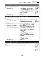
3
Detective cylinder-#1 ignition coil.
Execute the diagnostic mode (code No. d:30).
Test the primary and secondary coils for continuity.
Replace if defective.
Refer to “IGNITION SYSTEM” in CHAPTER 8.
4
Malfunction in ECU.
Replace the ECU.
FUEL INJECTION SYSTEM
Summary of Contents for Vector RS90GTZ
Page 1: ......
Page 74: ...INSP ADJ 2 51 Rear RST90GTZ Nipple Nipple both sides LUBRICATION ...
Page 329: ...FI 7 2 Passenger grip warmer relay RS90GTZ RS90LTGTZ RST90GTZ FUEL INJECTION SYSTEM ...
Page 330: ...FI 7 3 CIRCUIT DIAGRAM RS90GTZ RS90LTGTZ FUEL INJECTION SYSTEM ...
Page 332: ...FI 7 5 CIRCUIT DIAGRAM RST90GTZ FUEL INJECTION SYSTEM ...
Page 368: ...ELEC 8 2 IGNITION SYSTEM CIRCUIT DIAGRAM RS90GTZ RS90LTGTZ IGNITION SYSTEM ...
Page 370: ...ELEC 8 4 CIRCUIT DIAGRAM RST90GTZ IGNITION SYSTEM ...
Page 393: ...ELEC 8 27 CHARGING SYSTEM ...
Page 394: ...ELEC 8 28 LIGHTING SYSTEM CIRCUIT DIAGRAM RS90GTZ RS90LTGTZ LIGHTING SYSTEM ...
Page 396: ...ELEC 8 30 CIRCUIT DIAGRAM RST90GTZ LIGHTING SYSTEM ...
Page 404: ...ELEC 8 38 SIGNAL SYSTEM CIRCUIT DIAGRAM RS90GTZ RS90LTGTZ SIGNAL SYSTEM ...
Page 406: ...ELEC 8 40 CIRCUIT DIAGRAM RST90GTZ SIGNAL SYSTEM ...
Page 419: ...ELEC 8 53 SIGNAL SYSTEM ...
Page 420: ...ELEC 8 54 GRIP WARMER SYSTEM CIRCUIT DIAGRAM RS90GTZ RS90LTGTZ GRIP WARMER SYSTEM ...
Page 422: ...ELEC 8 56 CIRCUIT DIAGRAM RST90GTZ GRIP WARMER SYSTEM ...
Page 430: ...ELEC 8 64 COOLING SYSTEM CIRCUIT DIAGRAM RS90GTZ RS90LTGTZ COOLING SYSTEM ...
Page 458: ...SPEC 9 25 CABLE ROUTING CABLE ROUTING ...
Page 460: ...SPEC 9 27 CABLE ROUTING ...
Page 462: ...SPEC 9 29 RS90GTZ RS90LTGTZ CABLE ROUTING ...
Page 464: ...SPEC 9 31 RS90GTZ RS90LTGTZ CABLE ROUTING ...
Page 466: ...SPEC 9 33 RST90GTZ CABLE ROUTING ...
Page 468: ...SPEC 9 35 RST90GTZ CABLE ROUTING ...
Page 470: ...SPEC 9 37 RST90GTZ CABLE ROUTING ...
Page 472: ...SPEC 9 39 RS90GTZ RS90LTGTZ CABLE ROUTING ...
Page 474: ...SPEC 9 41 RS90GTZ RS90LTGTZ CABLE ROUTING ...
Page 476: ...SPEC 9 43 RST90GTZ CABLE ROUTING ...
Page 478: ...SPEC 9 45 RST90GTZ CABLE ROUTING ...
Page 480: ...SPEC 9 47 CABLE ROUTING ...
Page 482: ...SPEC 9 49 CABLE ROUTING ...
Page 484: ...SPEC 9 51 RS90GTZ RS90LTGTZ CABLE ROUTING ...
Page 486: ...SPEC 9 53 RST90GTZ CABLE ROUTING ...
Page 488: ...SPEC 9 55 RS90GTZ RS90LTGTZ CABLE ROUTING ...
Page 490: ...SPEC 9 57 RST90GTZ CABLE ROUTING ...
Page 492: ...SPEC 9 59 RST90GTZ CABLE ROUTING ...
Page 498: ......
Page 499: ......
Page 500: ......
Page 501: ...WIRING DIAGRAM 2010 RS90GTZ RS90LTGTZ 8JA 0F001 00 ...
Page 502: ...WIRING DIAGRAM 2010 RST90GTZ 8HF 0F001 00 ...
Page 503: ...WIRING DIAGRAM 2010 RS90GTZ RS90LTGTZ 8JA 0F001 00 ...


