background image

FI

7-27

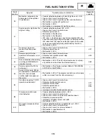
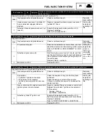
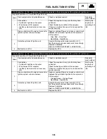
Fault code No.

43

Symptom Power supply to the fuel injectors and fuel pump is not normal.

Diagnostic code No. d:09 (fuel system voltage)

Order

Item/components and probable cause

Check or maintenance job

Reinstate-
ment method

1

Connections
• Fuel injection system relay coupler
• Wire harness ECU coupler

Check the couplers for any pins that may have 
pulled out.
Check the locking condition of the couplers.
If there is a malfunction, repair it and connect the 
coupler securely.

Setting the 
engine stop 
switch to 
“RUN” and 
turning the 
main switch 
on.

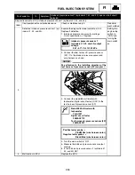
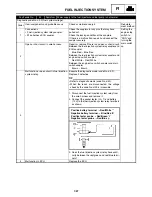
2

Open or short circuit in wire harness.

Repair or replace if there is an open or short circuit.
Between the fuel injection system relay coupler and 
ECU coupler.

Blue/Red – Blue/Red

Between the fuel injection system relay coupler and 
engine stop switch coupler.

Red/White – Red/White

Between the engine stop switch coupler and main 
switch coupler.

Brown – Brown

3

Malfunction or open circuit in fuel injection 
system relay.

Execute the diagnostic mode (code No. d:09).
Replace if defective.

TIP

• Refer to diagnostic mode (code No. d:50).
• When the leads are disconnected, the voltage

check by the code No. d:09 is impossible.

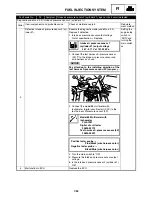
1. Disconnect the fuel injection system relay from 

the wire harness and remove it.

2. Connect the pocket tester (


×

 1) and battery 

(12 V) to the fuel injection system relay terminals 
as shown.

3. Does the fuel injection system relay have conti-

nuity between the red/green and red/blue termi-
nals?

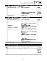
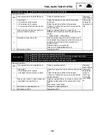
4

Malfunction in ECU.

Replace the ECU.

Positive battery terminal 

 Red/White 

Negative battery terminal 

 Blue/Red 

Positive tester probe 

 Red/Green 

Negative tester probe 

 Red/Blue 

FUEL INJECTION SYSTEM

Summary of Contents for Vector RS90GTZ

Page 1: ......

Page 2: ... 2009 by Yamaha Motor Corporation U S A 1st Edition April 2009 All rights reserved Any reprinting or unauthorized use without the written permission of Yamaha Motor Corporation U S A is expressly prohibited Printed in U S A P N LIT 12618 02 91 ...

Page 3: ...9cm3 Fuel system type Electronic fuel injection Track length 3 072 mm 121 in 3 456 mm 136 in 3 648 mm 144 in Front suspension Independent double wishbone Front shock absorber 40mm GYTR aluminum HPG with reservoir dual clicker Rear suspension Mono Shock II RA Mono Shock II RA 136 Pro Comfort CK 144 Rear shock absorber Front 40mm aluminum HPG Rear 46mm KYB aluminum HPG with remote adjust 40mm alumin...

Page 4: ... with the most satisfaction from his snowmobile and to conform to federal environmental quality objectives Yamaha Motor Company Ltd is continually striving to improve all of its models Modifications and significant changes in specifications or procedures will be forwarded to all authorized Yamaha deal ers and will appear in future editions of this manual where applicable TIP This Service Manual co...

Page 5: ...p of each page except in Chapter 3 PERIODIC INSPECTION AND ADJUSTMENT where the sub section title s appears Sub section titles appear in smaller print than the section title To help identify parts and clarify procedure steps there are exploded diagrams at the start of each removal and disassembly section Numbers are given in the order of the jobs in the exploded diagram A number indicates a disas ...

Page 6: ...which appear Filling fluid Lubricant Tightening torque Wear limit clearance Engine speed Special tool Electrical data Ω V A Illustrated symbols to in the exploded diagram indicate grade of lubricant and loca tion of lubrication point Apply locking agent LOCTITE Apply Yamabond No 5 Apply engine oil Apply gear oil Apply molybdenum disulfide oil Apply brake fluid Apply wheel bearing grease Apply low ...

Page 7: ...NERAL INFORMATION GEN INFO 1 PERIODIC INSPECTION AND ADJUSTMENT INSP ADJ 2 CHASSIS CHAS 3 POWER TRAIN POWR TR 4 ENGINE ENG 5 COOLING SYSTEM COOL 6 FUEL INJECTION SYSTEM FI 7 ELECTRICAL ELEC 8 SPECIFICATIONS SPEC 9 ...

Page 8: ...CTION 2 4 COOLING SYSTEM 2 4 VALVE CLEARANCE ADJUSTMENT 2 10 THROTTLE BODY SYNCHRONIZATION 2 16 THROTTLE CABLE FREE PLAY ADJUSTMENT 2 18 THROTTLE OVERRIDE SYSTEM T O R S CHECK 2 19 COMPRESSION PRESSURE MEASUREMENT 2 20 ENGINE OIL LEVEL INSPECTION 2 22 ENGINE OIL REPLACEMENT 2 23 CRANKCASE BREATHER HOSE INSPECTION 2 27 CYLINDER HEAD BREATHER HOSE INSPECTION 2 27 OIL TANK BREATHER HOSE INSPECTION 2 ...

Page 9: ...TEERING 3 8 STEERING RS90GTZ RS90LTGTZ 3 8 STEERING RST90GTZ 3 10 REMOVAL 3 14 INSPECTION 3 14 INSTALLATION 3 15 SKI 3 20 SKI 3 20 INSPECTION 3 21 FRONT SUSPENSION 3 22 HANDLING THE FRONT SHOCK ABSORBER AND GAS CYLINDER 3 24 DISPOSING OF A FRONT SHOCK ABSORBER AND GAS CYLINDER 3 24 INSPECTION 3 24 INSTALLATION 3 25 CHAPTER 4 POWER TRAIN PRIMARY SHEAVE AND DRIVE V BELT 4 1 REMOVAL 4 4 DISASSEMBLY 4...

Page 10: ...CYLINDER 4 76 INSPECTION 4 77 ASSEMBLY 4 78 INSTALLATION 4 79 TROUBLESHOOTING 4 79 FRONT AXLE AND TRACK 4 82 INSPECTION 4 83 INSTALLATION 4 83 CHAPTER 5 ENGINE FUEL TANK 5 1 REMOVAL 5 2 INSPECTION 5 2 INSTALLATION 5 3 EXHAUST PIPE AND MUFFLER 5 5 INSTALLATION 5 7 OIL TANK 5 9 ENGINE ASSEMBLY 5 10 LEADS AND HOSES 5 10 ENGINE ASSEMBLY 5 13 REMOVAL 5 15 INSTALLATION 5 15 CAMSHAFTS 5 17 CYLINDER HEAD ...

Page 11: ...NTAKE AIR TEMPERATURE SENSOR 7 31 ISC IDLE SPEED CONTROL UNIT 7 32 THROTTLE BODY 7 33 INJECTORS 7 35 REMOVAL 7 36 INSPECTION 7 36 FUEL PRESSURE INSPECTION 7 37 INSPECTION AND ADJUSTMENT 7 38 CHAPTER 8 ELECTRICAL SWITCH INSPECTION 8 1 SWITCH INSPECTION 8 1 INSPECTING A SWITCH SHOWN IN THE MANUAL 8 1 IGNITION SYSTEM 8 2 CIRCUIT DIAGRAM RS90GTZ RS90LTGTZ 8 2 CIRCUIT DIAGRAM RST90GTZ 8 4 TROUBLESHOOTI...

Page 12: ...T DIAGRAM RST90GTZ 8 56 TROUBLESHOOTING 8 58 GRIP THUMB WARMER ADJUSTMENT SWITCH 8 59 GRIP WARMER AND THUMB WARMER 8 61 GRIP THUMB WARMER ADJUSTMENT SWITCH 8 61 PASSENGER GRIP WARMER RST90GTZ 8 62 PASSENGER GRIP WARMER SWITCH RST90GTZ 8 62 PASSENGER GRIP WARMER RELAY RST90GTZ 8 63 COOLING SYSTEM 8 64 CIRCUIT DIAGRAM RS90GTZ RS90LTGTZ 8 64 TROUBLESHOOTING 8 66 RADIATOR FAN MOTOR RS90GTZ RS90LTGTZ 8...

Page 13: ...me serial number is located on the right hand side of the frame just below the front of the seat ENGINE SERIAL NUMBER The engine serial number is located on the right hand side of the crankcase TIP Designs and specifications are subject to change without notice SNOWMOBILE IDENTIFICATION ...

Page 14: ...arts must be reused or replaced as an assembly 4 During disassembly of the snowmobile clean all parts and place them in trays in the order of disassembly This will speed up assembly time and help ensure that all parts are reinstalled correctly 5 Keep all parts away from any source of fire 6 Be sure to keep to the tightening torque specifications When tightening bolts nuts and screws start with tho...

Page 15: ...rs facing outwards In other words the stamped letters must be on the side exposed to view When installing oil seals apply a light coating of lightweight lithium base grease to the seal lips Oil the bearings liberally when installing NOTICE Do not use compressed air to spin the bearings dry This causes damage to the surface of the bearings CIRCLIPS All circlips should be inspected carefully before ...

Page 16: ... Connector 2 Inspect Lead Coupler Connector Moisture Dry with an air blower Rust stains Connect and disconnect several times 3 Inspect All connections Loose connection Connect properly TIP If the pin on the terminal is flattened bend it up 4 Connect Lead Coupler Connector TIP Make sure all connections are tight IMPORTANT INFORMATION ...

Page 17: ...ve Handle with care and do not give impact Mankind has static electricity and it s voltage is very high and elec tronic parts is very sensitive It has possibility that inside small parts of electronic parts is destroyed by static electricity Do not touch and do not make it dirty When you disconnect electronic parts from wire harness always turn off main switch If you disconnect above condition it ...

Page 18: ...00 9 Thickness gauge P N 90890 03180 This gauge is used for clearance measurements Dial indicator gauge P N YU A8428 Dial gauge P N 90890 03097 This gauge is used for runout measurements Angle gauge Use goods on the market This gauge is used to tighten to specified angles Steering linkage alignment plate P N YS 01487 Steering link holder P N 90890 01487 Locks steering relay arms in place while adj...

Page 19: ... P N YM 01469 90890 01469 This tool is needed to loosen or tighten the oil filter cartridge Carburetor synchronizer P N YU 44456 Vacuum gauge P N 90890 03094 This tool is used to synchronize the throttle bodies Engine compression tester P N YU 33223 Compression gauge P N 90890 03081 This tool is used to measure engine compression Valve spring compressor P N YM 04019 90890 04019 This tool is used t...

Page 20: ...04116 Valve guide remover ø4 5 P N 90890 04116 This tool is used to remove or install the valve guides Valve guide installer 4 5 mm P N YM 04117 Valve guide installer ø4 5 P N 90890 04117 This tool is used to install the valve guides Valve guide reamer 4 5 mm P N YM 04118 Valve guide reamer ø4 5 P N 90890 04118 This tool is used to rebore the new valve guides Valve lapping tool P N YM A8998 Valve ...

Page 21: ...heave holder P N 90890 01701 This tool is used to hold the primary sheave and AC magneto rotor Primary clutch puller P N YS 01881 A Primary fixed sheave puller M18 32 5 mm P N 90890 01556 This tool is used for removing the primary sheave Clutch spider separator P N YS 28890 C Clutch separator wrench P N 90890 01740 This tool is used when disassembling and assembling the primary sheave Clutch separ...

Page 22: ...90890 03176 This tool is needed to measure fuel pressure Pressure gauge P N YU 03153 90890 03153 This tool is used to measure fuel pressure FOR ELECTRICAL SERVICE Analog pocket tester P N YU 03112 C Pocket tester P N 90890 03112 This instrument is necessary for checking the electrical compo nents Digital tachometer Use goods on the market Recommended goods kaise SK 8401 This tool is used to check ...

Page 23: ... used to measure voltage of the pressure sensor Test harness TPS 3P P N 90890 03204 This tool is used to measure voltage of the throttle position sensor Test harness speed sensor 3P P N YU 03208 90890 03208 This tool is used to measure voltage of the speed sensor SPECIAL TOOLS ...

Page 24: ...lve clearance when engine is cold Every 40 000 km 25 000 mi Crankcase breather system Check breather hose for cracks or damage Replace if necessary Fuel line Check fuel hose for cracks or damage Replace if necessary Fuel injection Check synchronization Adjust if necessary Exhaust system Check for leakage Tighten or replace gasket if necessary ITEM REMARKS INITIAL EVERY 1 month or 800 km 500 mi 40 ...

Page 25: ...t operation is smooth Lubricate if necessary Disc brake installation Check for slight free play Lubricate shaft with specified grease as required Every 1 600 km 1 000 mi Slide runners Check for wear and damage Replace if necessary Extrovert sprocket wheels Check for wear and damage Replace if necessary Skis and ski runners Check for wear and damage Replace if necessary Steering system Check toe ou...

Page 26: ...r Replace the spark plug Normal color is medium to light tan 4 Measure Spark plug gap Out of specification Regap Use a wire thickness gauge If necessary clean the spark plugs with a spark plug cleaner Before installing a spark plug clean the gasket surface and spark plug surface 5 Install Spark plugs TIP Finger tighten the spark plug before torqu ing it to specification Spark plug gap 0 7 0 8 mm 0...

Page 27: ...INGS in CHAPTER 3 Fuel tank cover Refer to FUEL TANK in CHAPTER 5 2 Inspect Fuel hose Cracks damage Replace 3 Install Fuel tank cover Refer to FUEL TANK in CHAPTER 5 Headlight assembly Top cover Refer to COWLINGS in CHAPTER 3 COOLING SYSTEM Coolant replacement 1 Place the snowmobile on a level surface 2 Remove Side cover right Side under cover right Refer to COWLINGS in CHAPTER 3 SPARK PLUGS FUEL ...

Page 28: ...cap Slowly turn the cap counterclockwise until it stop This allows any residual pressure to escape When the hissing sound has stopped press down on the cap while turn ing it counterclockwise to remove it 4 Place an open container under the coolant hoses 5 Disconnect Thermostat outlet hose Radiator outlet hose RS90GTZ RS90LTGTZ Right heat exchanger inlet hose RST90GTZ RS90GTZ RS90LTGTZ RST90GTZ 6 D...

Page 29: ...lowed If coolant is swallowed induce vomiting immediately and get immediate medical attention If coolant splashes in your eyes thor oughly wash them with water and consult a doctor If coolant splashes on your skin or clothes quickly wash it away with soap and water 10 Connect Thermostat outlet hose Radiator outlet hose RS90GTZ RS90LTGTZ Right heat exchanger inlet hose RST90GTZ 11 Connect Rear heat...

Page 30: ...er containing impurities or oil 13 Bleed the air from the cooling system Refer to Air bleeding Recommended antifreeze High quality ethylene glycol antifreeze containing corrosion inhibitors Antifreeze water mixing ratio 3 2 60 40 Total amount RS90GTZ 5 6 L 5 92 US qt 4 93 Imp qt RS90LTGTZ 6 1 L 6 45 US qt 5 37 Imp qt RST90GTZ 5 4 L 5 71 US qt 4 75 Imp qt COOLING SYSTEM ...

Page 31: ...Air bleeding 1 Remove Lower rear cover 2 Bleed air from the cooling system Air bleeding steps Lift up the tail of the snowmobile Remove the bleed bolt on the rear heat exchanger While slowly adding coolant to the coolant filler drain the coolant until no more air bub bles appear Tighten the bleed bolt Radiator pressure tester YU 24460 01 Radiator cap tester 90890 01325 Radiator pressure tester ada...

Page 32: ... sure the snowmobile is securely supported with a suitable stand Do not exceed clutch engagement speed Drive line damage and excessive V belt wear could occur or the snowmobile could unexpectedly move forward if the clutch engages Operate the engine only in a well venti lated area Remove the coolant reservoir cap and bleed the cooling system again as described above No air bubbles OK Pour coolant ...

Page 33: ... to ENGINE OIL REPLACEMENT 2 Remove Fuel tank cover Refer to FUEL TANK in CHAPTER 5 Headlight assembly Air filter case Refer to COWLINGS in CHAPTER 3 Coolant recovery RS90GTZ RS90LTGTZ Refer to HEAT EXCHANGER in CHAP TER 6 Throttle body assembly Refer to THROTTLE BODY in CHAPTER 7 3 Remove Oil tank Refer to OIL TANK in CHAPTER 5 4 Remove Cylinder head cover Refer to CAMSHAFTS in CHAPTER 5 Timing m...

Page 34: ...und when the camshaft lobes are turned away from each other Measure the valve clearance with a feeler gauge set thickness gauge TIP If the valve clearance is incorrect record the measured reading Measure the valve clearance in the following sequence Valve clearance cold Intake valve 0 15 0 22 mm 0 0059 0 0087 in Exhaust valve 0 21 0 25 mm 0 0083 0 0098 in Feeler gauge set YU 26900 9 Thickness gaug...

Page 35: ...ts fasten a wire to the timing chain to retrieve it if it falls into the crankcase 7 Adjust Valve clearance Adjustment steps Remove the valve lifter and the valve pad with a valve lapping tool valve lapper TIP Cover the timing chain opening with a rag to prevent the valve pad from falling into the crankcase Make a note of the position of each valve lifter and valve pad so that they can be installe...

Page 36: ...lve pad number 148 thickness 1 48 mm 0 058 in Rounded value 150 Locate the rounded number of the original valve pad and the measured valve clearance in the valve pad selection table The point where the column and row intersect is the new valve pad number TIP The new valve pad number is only an approxi mation The valve clearance must be mea sured again and the above steps should be repeated if the ...

Page 37: ...e 150 pad with 160 pad Measured clearance INSTALLED PAD NUMBER 120 125 130 135 140 145 150 155 160 165 170 175 180 185 190 195 200 205 210 215 220 225 230 235 240 0 00 0 02 120 125 130 135 140 145 150 155 160 165 170 175 180 185 190 195 200 205 210 215 0 03 0 07 120 125 130 135 140 145 150 155 160 165 170 175 180 185 190 195 200 205 210 215 220 0 08 0 12 120 125 130 135 140 145 150 155 160 165 170...

Page 38: ...mshaft cap bolts Align the camshaft marks with the camshaft cap marks Rotate the crankshaft clockwise several turns to seat the parts Measure the valve clearance again If the valve clearance is still out of specifica tion repeat all of the valve clearance adjust ment steps until the specified clearance is obtained 8 Install Crankshaft end accessing screw Timing mark accessing screw 9 Install Cylin...

Page 39: ...stay Refer to THROTTLE BODY in CHAPTER 7 2 Remove Vacuum cap 3 Install Carburetor synchronizer vacuum gauge Digital tachometer Use goods on the market Recommended goods Kaise SK 8401 4 Start the engine and let it warm up for sev eral minutes and then let it run at specified engine idling speed 5 Adjust Throttle body synchronization Carburetor synchronizer YU 44456 Vacuum gauge 90890 03094 Engine i...

Page 40: ...ressure between two throttle bodies should not exceed 1 3 kPa 10 mmHg 0 4 inHg 6 Stop the engine and remove the measuring equipment 7 Adjust Throttle cable free play Refer to THROTTLE CABLE FREE PLAY ADJUSTMENT 8 Install Headlight stay Refer to THROTTLE BODY in CHAPTER 7 Headlight assembly Refer to COWLINGS in CHAPTER 3 Fuel tank cover Refer to FUEL TANK in CHAPTER 5 Vacuum pressure at engine idli...

Page 41: ...emove the headlight assembly and head light stay Refer to COWLINGS in CHAPTER 3 and THROTTLE BODY in CHAPTER 7 Loosen the locknut Turn the adjuster in direction or until the specified free play is obtained Tighten the locknut TIP After adjusting the free play turn the handlebar to right and left and make sure that the engine idling does not run faster Throttle cable free play 2 0 3 0 mm 0 08 0 12 ...

Page 42: ...ttle switch by putting your thumb above and forefinger below between the throttle lever pivot and engine stop switch housing While holding as described above press the throttle lever gradually The T O R S will be activated and the engine speed will be limited to less than the clutch engagement speed WARNING If the engine speed does not decrease to less than the clutch engagement speed stop the eng...

Page 43: ... in CHAP TER 6 4 Remove Spark plug NOTICE Before removing the spark plugs use com pressed air to blow away any dirt accumu lated in the spark plug wells to prevent it from falling into the cylinders 5 Install Engine compression tester compression gauge 6 Measure Compression pressure Above the maximum pressure Inspect the cylinder head valve surfaces and pis ton crown for carbon deposits Below the ...

Page 44: ...kPa 1 0 kgf cm2 14 5 psi 7 Install Spark plug Compression pressure with oil applied into cylinder Reading Diagnosis Higher than without oil Piston ring s wear or damage Repair Same as without oil Piston valves cylinder head gasket or piston possibly defective Repair Compression pressure at sea level Standard compression pressure at sea level Standard 1 650 kPa 16 5 kgf cm2 239 3 psi at 400 r min M...

Page 45: ...HAPTER 3 Disconnect the oil level switch coupler NOTICE Disconnect the oil level switch coupler before removing the oil level gauge Other wise the lead can twist and become sev ered Remove the oil level gauge wipe it clean insert it back into the filler hole without screwing it in and then remove it again to check the oil level The engine oil level should be between the maximum level mark H and mi...

Page 46: ...NOTICE Use only 4 stroke engine oil Engine oil also lubricates the starter clutch In order to prevent clutch slippage do not mix any chemical additives with the oil ENGINE OIL REPLACEMENT 1 Place the snowmobile on a level surface and apply the parking brake 2 Start the engine warm up for several min utes and then turn it off 3 Place a containers under the engine oil drain bolt and oil tank Recomme...

Page 47: ...90GTZ RS90LTGTZ Refer to HEAT EXCHANGER in CHAP TER 6 6 Disconnect Oil level gauge coupler Refer to ENGINE OIL LEVEL INSPEC TION 7 Remove Oil level gauge Refer to ENGINE OIL LEVEL INSPEC TION 8 Remove Cylinder head oil filler cap 9 Remove Oil pan engine oil drain bolt TIP A mark is stamped the oil pan near the oil pan engine oil drain bolt ENGINE OIL REPLACEMENT ...

Page 48: ...attached to the crankcase oil leakage may occur Apply a thin coat of engine oil onto the O ring of the new oil filter cartridge NOTICE Make sure that the O ring is positioned cor rectly in the groove of the oil filter car tridge Tighten the new oil filter cartridge to specifi cation with an oil filter wrench 13 Install Drain bolts along with the new gaskets Oil filter wrench YM 01469 90890 01469 O...

Page 49: ...l engine oil starts to seep from the oil check bolt If no engine oil comes out after one minute turn the engine off so that it will not seize Check the engine oil passages the oil filter and the oil pump for damage or leakage Start the engine after solving the problem s and check the engine oil pressure again Tighten the oil check bolt to specification 18 Install All removed parts TIP For installa...

Page 50: ...ctly 3 Install Side cover left Refer to COWLINGS in CHAPTER 3 CYLINDER HEAD BREATHER HOSE INSPECTION 1 Remove Headlight assembly Refer to COWLINGS in CHAPTER 3 2 Inspect Cylinder head breather hose Cracks damage Replace Loosen connection Connect properly NOTICE Make sure that the cylinder head breather hose is routed correctly 3 Install Headlight assembly Refer to COWLINGS in CHAPTER 3 CRANKCASE B...

Page 51: ...THROTTLE BODY JOINTS INSPECTION 1 Remove Fuel tank cover Refer to FUEL TANK in CHAPTER 5 Headlight assembly Refer to COWLINGS in CHAPTER 3 Headlight stay Refer to THROTTLE BODY in CHAPTER 7 2 Inspect Throttle body joints Cracks damage Replace the defective parts Refer to THROTTLE BODY in CHAPTER 7 3 Install Headlight stay Refer to THROTTLE BODY in CHAPTER 7 Headlight assembly Refer to COWLINGS in ...

Page 52: ...ase cover 3 Remove Air filter element frame Air filter element 4 Clean Air filter element TIP Remove the snow 5 Inspect Air filter element Damage clogs Replace 6 Install Air filter element Air filter element frame Air filter case cover 7 Install Headlight assembly Side cover left and right Shroud Refer to COWLINGS in CHAPTER 3 CHECKING THE AIR FILTER ELEMENT ...

Page 53: ... pipe Muffler band Exhaust pipe bands Cracks damage Replace Gasket Gaskets Gasket Exhaust gas leaks Replace 3 Inspect Tightening torque 4 Install All removed parts TIP For installation reverse the removal proce dure Exhaust pipe joint bolt 25 Nm 2 5 m kgf 18 ft lbf Muffler bolt 16 Nm 1 6 m kgf 11 ft lbf Exhaust pipe bolt 23 Nm 2 3 m kgf 17 ft lbf Muffler band bolt 20 Nm 2 0 m kgf 14 ft lbf Exhaust...

Page 54: ...on Adjust TIP Push the secondary sheave inward towards the frame and then measure the sheave off set 4 Adjust Sheave offset Adjustment steps Apply the parking brake to lock the second ary sheave Remove the secondary sheave bolt washer shim s left and secondary sheave Adjust the sheave offset by adding or remov ing shim s right Sheave offset 13 5 16 5 mm 0 53 0 65 in Adding shim Offset is increased...

Page 55: ... of specification Adjust 6 Adjust Secondary sheave free play clearance Adjustment steps Apply the parking brake to lock the second ary sheave Remove the secondary sheave bolt and washer Adjust the secondary sheave free play clear ance by adding or reducing a shim s left Secondary sheave bolt 64 Nm 6 4 m kgf 46 ft lbf Secondary sheave free play clearance 1 0 2 0 mm 0 04 0 08 in Feeler gauge set YU ...

Page 56: ...ing a shim on each adjusting bolt NOTICE As the V belt wears adjustment may be necessary To ensure proper clutch perfor mance the V belt position should be adjusted by adding a shim on each adjust ing bolt when the V belt position reaches 1 5 mm 0 06 in below the edge 1 Measure V belt position TIP Install the new V belt onto the secondary sheave only Do not force the V belt between the sheaves the...

Page 57: ... primary and secondary sheaves Use a rag soaked in lacquer thinner or solvent to remove the oil or grease and then check the primary and secondary sheaves V belt position Adjustment More than 1 5 mm 0 06 in above the edge Remove a shim From 1 5 mm 0 06 in above the edge to 0 5 mm 0 02 in below the edge Not necessary It is correct More than 0 5 mm 0 02 in below the edge Add shim Part number Thickne...

Page 58: ...orward Out of specification Adjust the primary sheave PARKING BRAKE PAD INSPECTION 1 Remove Side cover right Refer to COWLINGS in CHAPTER 3 2 Inspect Parking brake pad Wear limit reached Replace the park ing brake assembly 3 Install Side cover right Refer to COWLINGS in CHAPTER 3 V belt outside circumference 1 133 0 mm 44 61 in Engagement speed RS90GTZ RS90LTGTZ 3 100 3 500 r min RST90GTZ 2 900 3 ...

Page 59: ...djust 5 Adjust Brake pad clearance Adjustment steps Loosen the locknut Turn the adjuster in or out until the speci fied clearance between the parking brake pad and brake disc is obtained Tighten the locknut 6 Install Side cover right Refer to COWLINGS in CHAPTER 3 Parking brake cable distance 43 5 46 5 mm 1 713 1 831 in Turning in Distance is increased Turning out Distance is decreased Parking bra...

Page 60: ...s or plastic parts Always clean up spilled fluid immediately WARNING Use only the designated brake fluid Other fluids may deteriorate the rubber seals causing leakage and poor brake perfor mance Refill with the same type of fluid Mixing fluids may result in a harmful chemical reaction leading to poor brake perfor mance When refilling be careful that water does not enter the brake master cylinder r...

Page 61: ...INGS in CHAPTER 3 BRAKE HOSE INSPECTION 1 Remove Top cover Headlight assembly Refer to COWLINGS in CHAPTER 3 2 Inspect Brake hose Cracks damage wear Replace 3 Check Fluid leakage Apply the brake lever several times Fluid leakage Replace the defective parts 4 Install Headlight assembly Top cover Refer to COWLINGS in CHAPTER 3 Brake pad wear limit 4 7 mm 0 19 in RS90GTZ RS90LTGTZ 7 5 mm 0 30 in RST9...

Page 62: ...eservoir to overflow c Connect clear plastic hoses tightly to the brake caliper bleed screws d Place the other end of the hoses in a con tainer e Slowly apply the brake lever several times f Pull the lever in then hold the lever in posi tion g Loosen the bleed screws and allow the brake lever to travel towards its limit h Tighten the bleed screws when the brake lever limit has been reached then re...

Page 63: ...LINGS in CHAPTER 3 DRIVE CHAIN Oil level inspection WARNING The engine will be very hot after the engine has run Avoid touching a hot engine while they are still hot with any part of your body or clothing during inspection or repair 1 Remove Side cover right Refer to COWLINGS in CHAPTER 3 2 Place the snowmobile on a level surface 3 Check Oil level AIR BLEEDING HYDRAULIC BRAKE SYSTEM DRIVE CHAIN ...

Page 64: ...evels If not add oil to the upper level For models without reverse transmissions For models with reverse transmissions RS90GTZ RS90LTGTZ RST90GTZ NOTICE Make sure that no foreign material enters the drive chain housing Reinstall the dipstick TIP Align the notch of the dipstick handle with the projection of the drive chain housing Recommended oil SAE 75W or 80W API GL 3 Gear oil DRIVE CHAIN ...

Page 65: ...ve chain slack Adjustment steps Loosen the locknut Turn the adjusting bolt clockwise until it is finger tight and then loosen it 1 4 turn Hold the adjusting bolt in place while tight ening the chain adjusting locknut Drive chain housing oil drain bolt 16 Nm 1 6 m kgf 11 ft lbf Recommended oil SAE 75W or 80W API GL 3 Gear oil Oil capacity 0 25 L 0 26 US qt 0 22 Imp qt Drive chain adjusting locknut ...

Page 66: ...ating track Inspect the condition of the track fre quently Replace the track if it is damaged to a level where the fabric reinforcement material is visible 1 Lift the rear of the snowmobile onto a suit able stand to raise the track off the ground 2 Measure Track deflection Using a spring scale pull down on the center of the track with 100 N 10 kgf 22 lbf of force Out of specification Adjust 3 Adju...

Page 67: ...t f Recheck the alignment and deflection If necessary repeat steps c to e until the specified amount is obtained g Apply ESSO beacon 325 grease or Aero shell grease 7A to the rear axle nut RS90GTZ RS90LTGTZ h Tighten the rear axle nut Track alignment Shifted to right Shifted to left Left adjuster Turn out Turn in Right adjuster Turn in Turn out Track deflection More than specified Less than specif...

Page 68: ...PROCKET WHEELS RS90GTZ RS90LTGTZ 1 Inspect Extrovert sprocket wheels Cracks damage Replace 2 Measure Teeth a Measuring point 20 mm 0 79 in b Extrovert sprocket wheel wear limit Out of specification Replace Slide runner wear limit 10 5 mm 0 41 in Extrovert sprocket wheel wear limit 13 mm 0 51 in SLIDE RUNNER INSPECTION EXTROVERT SPROCKET WHEELS RS90GTZ RS90LTGTZ ...

Page 69: ...stained high speed usage in areas such as icy trails frozen lakes and rivers that have minimal snow coverage An overheated track will be weakened inter nally which may cause failure or damage Off trail riding Avoid off trail riding until there is sufficient snow coverage It generally takes several feet of snow to provide a good overall base to prop erly cover debris such as rocks logs etc If snow ...

Page 70: ... crete curbs etc STEERING SYSTEM Free play check 1 Check Steering system free play Move the handlebar up and down and back and forth Turn the handlebar slightly to the right and left Excessive free play Check that the han dlebar tie rod ends and relay rod ends are installed securely in position If free play still exists check the steering bearing front suspension links and ski mounting area for we...

Page 71: ... Refer to STEERING in CHAPTER 3 Loosen the locknuts tie rods Turn the tie rods in or out until the speci fied toe out is obtained Tighten the locknuts tie rods NOTICE After tightening the inside and outside ball joint locknuts make sure the tie rods can be rotated freely through the ball joint travel If not loosen the locknuts and reposition the ball joint so that the tie rods can be rotated freel...

Page 72: ...l cause poor brake performance LUBRICATION Brake lever throttle lever and throttle cable end 1 Lubricate the brake lever pivot throttle lever and the ends of the throttle cables WARNING Apply a dab of grease onto only the end of the cables Do not grease the throttle cables They could freeze and cause a loss of con trol Brake lever adjusting locknut 6 Nm 0 6 m kgf 4 3 ft lbf Recommended lubricant T...

Page 73: ...RONT SUSPENSION in CHAP TER 3 2 Use a grease gun to inject grease into the nipples and both sides 3 Apply grease to the pivoting parts Front Rear RS90GTZ Rear RS90LTGTZ Nipple Nipple both sides Recommended lubricant ESSO Beacon 325 grease or Aeroshell grease 7A LUBRICATION ...

Page 74: ...INSP ADJ 2 51 Rear RST90GTZ Nipple Nipple both sides LUBRICATION ...

Page 75: ...ulb until it has cooled down 5 Install Headlight bulb Secure the new headlight bulb with the headlight bulb holder NOTICE Avoid touching the glass part of the head light bulb to keep it free from oil otherwise the transparency of the glass the life of the bulb and the luminous flux will be adversely affected If the headlight bulb gets soiled thoroughly clean it with a cloth moistened with alcohol ...

Page 76: ...e start the engine and let it idle 5 Switch on the headlight s high beam and check the height of the projected beam on the wall The projection should be at the position marked in step 3 or 1 2 lower set range Distance Height Set range 6 Adjust Headlight beam vertically Adjustment steps Remove the top cover Refer to COWLINGS in CHAPTER 3 Turn the adjusting screw in direction or to adjust the headli...

Page 77: ...parks or open flames e g welding equipment lighted cigarettes DO NOT SMOKE when charging or han dling batteries KEEP BATTERIES AND ELECTROLYTE OUT OF REACH OF CHILDREN Avoid bodily contact with electrolyte as it can cause severe burns or permanent eye injury First aid in case of bodily contact External SKIN Wash with water EYES Flush with water for 15 minutes and get immediate medical attention In...

Page 78: ...explained in the charging method illustrations If the bat tery is overcharged the electrolyte level will drop considerably Therefore take special care when charging the battery TIP Since VRLA Valve Regulated Lead Acid bat teries are sealed it is not possible to check the charge state of the battery by measuring the specific gravity of the electrolyte Therefore the charge of the battery has to be c...

Page 79: ...when the open cir cuit voltage equals or exceeds 12 8 V Check the charge of the battery as shown in the charts and the following example Example Open circuit voltage 12 0 V Charging time 6 5 hours Charge of the battery 20 30 Open circuit voltage V Charging time hours Relationship between the open circuit voltage and the charging time at 20 C 68 F These values vary with the temperature the conditio...

Page 80: ...chance of sparks do not plug in the battery charger until the bat tery charger leads are connected to the battery Before removing the battery charger lead clips from the battery terminals be sure to turn off the battery charger Make sure that the battery charger lead clips are in full contact with the battery terminal and that they are not shorted A corroded battery charger lead clip may generate ...

Page 81: ...charging current is reached If the current does not exceed the standard charg ing current after 5 minutes replace the battery If charging requires more than 5 hours it is advisable to check the charging current after a lapse of 5 hours If there is any change in the amperage readjust the voltage to obtain the standard charging cur rent Measure the battery open circuit voltage after leaving the batt...

Page 82: ...nt is higher than the stand ard charging current writ ten on the battery Charge the battery until the battery s charging voltage is 15 V This type of battery charger cannot charge the VRLA Valve Regulated Lead Acid battery A variable volt age charger is recommended Measure the battery open circuit voltage after leaving the battery unused for more than 30 minutes 12 8 V or more Charging is complete...

Page 83: ...egative battery lead 9 Check Battery terminals Dirt Clean with a wire brush Loose connection Connect properly 10 Lubricate Battery terminals 11 Install the battery cover and then hook the battery band 12 Install All removed parts TIP For installation reverse the removal proce dure Recommended lubricant Dielectric grease BATTERY INSPECTION ...

Page 84: ...ecking or replacing a fuse 1 Inspect Continuity Inspection steps Connect the analog pocket tester pocket tester to the fuse and check the continuity TIP Set the analog pocket tester pocket tester selector to Ω 1 If the analog pocket tester pocket tester indicates replace the fuse Analog pocket tester YU 03112 C Pocket tester 90890 03112 FUSE INSPECTION ...

Page 85: ...ARNING Never use a fuse with an amperage other than that specified Improvising or using a fuse with the wrong amperage rating may cause extensive damage to the electrical system cause the lighting ignition grip warmer signal and meter systems to mal function and could possibly cause a fire RS90GTZ RS90LTGTZ RST90GTZ Item Amperage Q ty Main fuse 40 A 1 Fuel injection system fuse 10 A 1 Ignition fus...

Page 86: ...op Shifting speed is defined as the engine speed reached when the snowmobile has travelled 800 m 2 500 ft after being started at full throt tle from a dead stop Normally when a snowmobile reaches shifting speed the snowmobile speed increases but the engine speed remains nearly constant Under unfavorable conditions wet snow icy snow hills or rough terrain however engine speed may decrease after the...

Page 87: ...nt speed and shifting speed is necessary This setting is called high altitude tuning The following changes are usually performed in high altitude tuning To increase the clutch engagement and shift ing speed changing to a larger spring con stant or using lighter weights and rivets decreasing primary sheave thrust Increasing the reduction ratio of the driven gear drive gear increasing the driving pe...

Page 88: ...ng reaction force Spring rate A larger spring rate increases the shifting speed It also slightly increases the clutch engagement speed Shifting tends to become somewhat harder increasing the spring reaction force A smaller spring rate decreases the shifting speed It also slightly decreases the clutch engagement speed Shifting tends to become somewhat easier decreasing the spring reaction force Wei...

Page 89: ...thrust A larger diameter increases the clutch engage ment speed decreasing the sheave thrust Shim Quantity Using more shims increases the preload and clutch engagement speed increasing the spring reaction force Using less shim decreases the preload and clutch engagement speed decreasing the spring reaction force Secondary sheave Spring Preload Spring rate compression torsion A larger preload sprin...

Page 90: ... shifting harder The shifting speed tends to decrease and shifting becomes somewhat easier decreasing the sheave thrust Shim Quantity Size of the secondary sheave clearance between fixed sheave and sliding sheave can be adjusted by the number of shims used Adjust the clearance when the V belt wear deterio rates and belt width becomes smaller Using more shims makes secondary sheave clearance smalle...

Page 91: ...59 5 2 34 5 25 91 2 3 59 Yellow Green Yellow 90501 582L7 24 5 2 50 392 40 5 8 0 228 59 5 2 34 4 92 89 4 3 52 Blue White Blue 90501 583L0 19 6 2 00 441 45 5 8 0 228 59 5 2 34 5 65 95 9 3 78 White White White 90501 583L1 22 1 2 25 441 45 5 8 0 228 59 5 2 34 5 25 93 4 3 68 RS90LTGTZ White Silver White 90501 583L4 22 1 2 25 343 35 5 8 0 228 59 5 2 34 5 25 89 0 3 50 White Pink White 90501 583L5 22 1 2 ...

Page 92: ... and rivets Shape ID mark Standard 8DJ 17605 00 37 77 1 333 8DN 17605 30 39 76 1 404 8ES 17605 00 54 63 1 928 8FA 17605 10 63 81 2 252 8FN 17605 00 75 28 2 657 8FP 17605 00 67 81 2 394 RS90GTZ RS90LTGTZ 8FS 17605 00 65 52 2 313 8GC 17605 00 47 28 1 669 CLUTCH ...

Page 93: ...rce Decreased force 90269 06006 Steel with hole 17 2 0 677 3 6 0 127 OUT RS90GTZ RS90LTGTZ 90261 06034 Steel 13 9 0 547 3 6 0 127 90261 06019 Steel 13 3 0 524 3 1 0 109 IN RS90GTZ RS90LTGTZ CENTER RS90GTZ RS90LTGTZ 90266 06002 Steel with hole 13 3 0 524 2 44 0 086 IN RST90GTZ CENTER RST90GTZ OUT RST90GTZ 90261 06015 Steel 10 3 0 406 2 44 0 086 90261 06028 Aluminum 10 3 0 406 0 85 0 030 90266 06001...

Page 94: ...ved Machined Increased force Decreased force 8FG 17624 10 15 0 0 591 Grooved 8FG 17624 20 15 6 0 614 No Mark RST90GTZ 8FG 17624 30 16 0 0 630 Grooved Grooved 8FG 17624 40 16 5 0 650 Machined RS90GTZ RS90LTGTZ 14 6 mm 0 57 in 14 6 mm 0 57 in 14 6 mm 0 57 in 14 6 mm 0 57 in 14 6 mm 0 57 in Part number Thickness mm in Standard 90201 483P9 1 0 0 039 None RS90GTZ RS90LTGTZ RST90GTZ CLUTCH ...

Page 95: ...5 2 95 69 5 2 74 Green 90508 556A2 8314 848 8 5 0 87 48 53 5 5 0 217 5 53 75 2 95 69 5 2 74 Silver 90508 556A7 9460 965 10 2 1 04 58 24 5 5 0 217 4 86 75 2 95 69 5 2 74 Pink 90508 60012 11876 1211 12 3 1 26 70 23 6 0 0 236 5 53 75 2 95 69 5 2 74 RST90GTZ Pink Pink 90508 60018 11876 1211 12 3 1 26 70 23 6 0 0 236 5 53 75 2 95 69 5 2 74 RS90GTZ RS90LTGTZ White 90508 60007 12654 1290 13 5 1 38 77 08 ...

Page 96: ...17604 00 51 43 Quicker up shifting during acceleration Quicker back shifting under load 8BV71 8BV 17604 71 47 8BV51 8BV 17604 51 45 8BV31 8BV 17604 31 43 RS90GTZ RS90LTGTZ 8BV11 8BV 17604 11 41 RST90GTZ 8BV91 8BV 17604 91 39 Part number Thickness mm in Standard 90201 061H1 0 5 0 020 90201 06037 1 0 0 039 RS90GTZ RS90LTGTZ RST90GTZ CLUTCH ...

Page 97: ...bers designate the number of links in the chain Part name Teeth links Part number Standard Drive sprocket 18 teeth 8FA 17682 80 19 teeth 8FA 17682 90 20 teeth 8FA 17682 00 21 teeth 8FA 17682 10 22 teeth 8FA 17682 20 23 teeth 8FA 17682 30 RST90GTZ 24 teeth 8FA 17682 40 RS90GTZ RS90LTGTZ Driven sprocket 38 teeth 8FB 47587 80 RS90GTZ 39 teeth 8FB 47587 90 RS90LTGTZ RST90GTZ 40 teeth 8FB 47587 00 Chai...

Page 98: ...ad 441 N 45 kgf 99 lbf 392 N 40 kgf 88 lbf Spring rate 27 0 N mm 2 75 kgf mm 154 2 lbf in 29 4 N mm 3 00 kgf mm 168 2 lbf in Wire diameter 6 0 mm 0 236 in Outside diameter 59 5 mm 2 34 in Weight ID 8FP 17605 00 8FP00 Weight rivet Steel with hole 17 2 OUT Steel 13 3 OUT Steel with hole 13 3 OUT None OUT Steel 13 3 CENTER Steel with hole 13 3 CENTER Aluminum with hole 13 3 CENTER None CENTER Steel 1...

Page 99: ...45 kgf 99 lbf 392 N 40 kgf 88 lbf Spring rate 22 1 N mm 2 25 kgf mm 126 2 lbf in 29 4 N mm 3 00 kgf mm 168 2 lbf in Wire diameter 5 8 mm 0 228 in 6 0 mm 0 236 in Outside diameter 59 5 mm 2 34 in Weight ID 8FP 17605 00 8FP00 Weight rivet Steel with hole 17 2 OUT Steel 13 3 OUT Aluminum with hole 13 3 OUT None OUT Steel 13 3 CENTER Aluminum with hole 13 3 CENTER None CENTER Steel 13 3 IN None IN Ste...

Page 100: ...N 30 kgf 66 lbf Spring rate 29 4 N mm 3 0 kgf mm 167 9 lbf in 31 9 N mm 3 25 kgf mm 182 1 lbf in Wire diameter 6 0 mm 0 236 in Outside diameter 59 5 mm 2 34 in Weight ID 8HF 17605 00 8HF00 8ES 17605 00 8ES00 Weight rivet Steel with hole 13 3 OUT None OUT Steel 17 2 OUT Steel 13 3 OUT Steel 10 3 OUT Steel with hole 13 3 CENTER None CENTER Not applicable CENTER Steel with hole 13 3 IN Steel 17 2 IN ...

Page 101: ...eat distance Standard Short Long Preload Hard Soft Length Min 246 6 mm 9 71 in 256 6 mm 10 10 in Max 256 6 mm 10 10 in Spring seat distance Standard Short Long Preload Hard Soft Length Min 246 5 mm 9 70 in 256 5 mm 10 10 in Max 256 5 mm 10 10 in Spring seat distance Standard Short Long Preload Hard Soft Length Min 243 0 mm 9 57 in 253 0 mm 9 96 in Max 253 0 mm 9 96 in Shock absorber spring preload...

Page 102: ...force adjustment The rebound damping force can be adjusted by turning the adjusting knob RS90GTZ RS90LTGTZ RST90GTZ With the adjusting knob fully turned lightly in direction Adjuster knob position 20 clicks out 12 clicks out 3 clicks out Minimum Standard Maximum Direction Direction Rebound damping force Soft Hard Adjuster knob position 20 clicks out 7 clicks out 3 clicks out Minimum Standard Maxim...

Page 103: ...g forces for the left and right ski shock absorbers must be adjusted to the same settings Uneven settings can cause poor handling and loss of stability Compression damping force adjustment The compression damping force can be adjusted by turning the adjusting knob RS90GTZ RS90LTGTZ RST90GTZ With the adjusting knob fully turned lightly in direction Adjuster knob position 12 clicks out 7 clicks out ...

Page 104: ...ge in the com pression damping force Be sure to stop the adjusting knob at a position where there is a click The damping forces for the left and right ski shock absorbers must be adjusted to the same settings Uneven settings can cause poor handling and loss of stability REAR SUSPENSION Limiter strap 1 Adjust Limiter strap length NOTICE Make sure the left and right rear suspen sion limiter straps a...

Page 105: ...ork better in one condition but only at the expense of another Keep this in mind when you adjust the suspension RS90GTZ RS90LTGTZ RST90GTZ Standard setting RS90GTZ RS90LTGTZ No 2 hole RST90GTZ No 1 hole Limiter strap nut 4 Nm 0 4 m kgf 2 9 ft lbf No 5 hole No 4 hole shortest No 1 hole longest More weight on skis Heavy steering oversteer More maneuverability Favors hardpack snow ice smooth trails t...

Page 106: ...ly pres surized nitrogen gas Do not tamper with or attempt to open the shock absorber assemblies Do not subject the shock absorber assem blies to flames or high heat which could cause it to explode Spring seat distance Standard Short Long Preload Hard Soft Length Min 187 0 mm 7 36 in 197 0 mm 7 76 in Max 197 0 mm 7 76 in Shock absorber spring preload adjusting locknut 42 Nm 4 2 m kgf 30 ft lbf REA...

Page 107: ...roper position by the tool WARNING Always adjust both spring preload left and right to the same setting Uneven adjust ment can cause poor handling and loss of stability Springadjuster position 1 2 3 4 5 6 7 Preload Soft Hard Standard 4 Spring adjuster position S M H Spring rate Soft Medium Hard Standard M REAR SUSPENSION ...

Page 108: ... and injury With the adjusting knob fully turned lightly in direction NOTICE Be sure to stop the remote adjustment dial at a marked position around the dial where there is a click WARNING These shock absorber contain highly pres surized nitrogen gas Do not tamper with or attempt to open the shock absorber assemblies Do not subject the shock absorber assem blies to flames or high heat which could c...

Page 109: ...e than 12 clicks Even if the adjust ing knob is continually turned after 12 clicks there will be no change in the com pression damping force Be sure to stop the adjusting knob at a position where there is a click WARNING These shock absorber contain highly pres surized nitrogen gas Do not tamper with or attempt to open the shock absorber assemblies Do not subject the shock absorber assem blies to ...

Page 110: ...curely tighten the locknut NOTICE When using the special wrench make sure that it is situated at a right angle to the con trol rod and that it is tightly fitted to the locknut or the control rod adjuster WARNING Never adjust the control rod beyond the range of the scale on the special wrench RST90GTZ 1 Adjust Control rod stroke NOTICE Make sure the adjusting nut ends are set at the same position o...

Page 111: ...G Never adjust the control rods beyond the maximum range indicated on the rods with red paint While holding the adjusting nut securely tighten the locknut Adjusting nut position 1 2 3 Effect Increase weight transfer Decrease weight transfer Standard 2 Control rod adjusting locknut 25 Nm 2 5 m kgf 18 ft lbf REAR SUSPENSION ...

Page 112: ...t of the snowmobile darts from side to side on a straight away Too much weight on skis Extend limiter straps and or increase center shock spring preload or reduce rear shock spring preload or reduce front shock spring preload Skis out of alignment Adjust ski toe out Loose steering ball joints Replace worn ball joints Too much carbide on ski run ners Use ski runners with less car bide Under steerin...

Page 113: ...inding or dam aged joint linkage bushings Check for free movement of stabilizer bar Check the condi tion of the joint linkage bushing and replace as necessary Control rod adjusted to pro vide too much weight transfer Adjust control rod to allow less weight transfer Too much front shock spring preload and or the spring used is too stiff Reduce spring preload and or select a softer spring Center sho...

Page 114: ...ing Inspect for free movement of rear suspension linkages and arms Replace damaged com ponents and apply grease to all pivot areas Limiter straps length has been shortened Lengthen limiter straps length Control rod adjustment does not provide enough weight transfer Adjust control rod to allow more weight transfer Not enough weight transfer Track won t hook up Not enough center shock spring preload...

Page 115: ...rt name Q ty Remarks Covers removal Remove the parts in the order listed below 1 Shroud 1 2 Side cover left and right 2 3 Side under cover left and right 2 For installation reverse the removal procedure 3 Nm 0 3 m kgf 2 2 ft lbf 7 Nm 0 7 m kgf 5 1 ft lbf COWLINGS ...

Page 116: ... the order listed below 1 Windshield 1 2 Fairing 1 3 Top cover 1 4 Main switch 1 5 Auxiliary DC jack 1 6 Headlight side cover left and right 2 7 Headlight cover 1 8 Speedometer coupler 1 Disconnect 9 Speedometer 1 10 Headlight coupler 2 Disconnect 11 Headlight 1 For installation reverse the removal procedure 3 Nm 0 3 m kgf 2 2 ft lbf COWLINGS ...

Page 117: ...Windshield cover 1 4 Wind deflector left and right 2 5 Windshield rearview mirror stay 1 6 Top cover 1 7 Main switch 1 8 Auxiliary DC jack 1 9 Headlight side cover left and right 2 10 Speedometer coupler 1 Disconnect 11 Headlight cover 1 12 Speedometer 1 13 Headlight coupler 2 Disconnect 14 Headlight 1 For installation reverse the removal procedure 3 Nm 0 3 m kgf 2 2 ft lbf 14 Nm 1 4 m kgf 10 ft l...

Page 118: ...ake air temperature sensor 1 3 Air filter case cover 1 4 Air filter element frame 1 5 Air filter element 1 6 Air filter case joint clamp screw 3 Loosen 7 Oil tank breather hose 1 Disconnect 8 Cylinder head breather hose 1 Disconnect 9 ISC idle speed control unit inlet hose 1 Disconnect 10 Air filter case 1 For installation reverse the removal procedure 3 Nm 0 3 m kgf 2 2 ft lbf COWLINGS ...

Page 119: ...wer rear cover 1 2 Muffler end cap 2 3 Tail brake light cover 1 4 Tail brake light holder 1 5 Tail brake light sub wire harness coupler 1 Disconnect 6 Seat 1 7 Tail brake light 1 8 Tail brake light coupler 1 Disconnect 9 Muffler side cover 2 For installation reverse the removal procedure 7 Nm 0 7 m kgf 5 1 ft lbf 18 Nm 1 8 m kgf 13 ft lbf 4 Nm 0 4 m kgf 2 9 ft lbf SEAT Refer to COWLINGS Refer to F...

Page 120: ...over rubber seal left and right 2 4 Passenger grip warmer coupler left and right 2 Disconnect 5 Passenger grip warmer left and right 2 6 Passenger grip warmer switch coupler 1 Disconnect 7 Backrest side cover left and right 2 8 Passenger grip warmer switch 1 For installation reverse the removal procedure 7 Nm 0 7 m kgf 5 1 ft lbf 26 Nm 2 6 m kgf 19 ft lbf 48 Nm 4 8 m kgf 35 ft lbf BACKREST AND SEA...

Page 121: ...ment 1 6 Lower rear cover 1 7 Muffler end cap 2 8 Tail brake light cover 1 9 Tail brake light coupler 1 Disconnect 10 Tail brake light 1 11 Muffler side cover left and right 2 12 Tail brake light holder 1 13 Storage compartment bracket 1 For installation reverse the removal procedure 16 Nm 1 6 m kgf 11 ft lbf 7 Nm 0 7 m kgf 5 1 ft lbf 13 Nm 1 3 m kgf 9 4 ft lbf 18 Nm 1 8 m kgf 13 ft lbf 19 Nm 1 9 ...

Page 122: ... ROUTING in CHAPTER 9 5 Grip warmer lead coupler 2 Disconnect 6 Throttle switch lead coupler 2 Disconnect 7 Engine stop switch lead coupler 1 Disconnect 8 Thumb warmer lead coupler 1 Disconnect 9 Helmet shield heater jack lead coupler 1 Disconnect 10 Brake light switch lead coupler 1 Disconnect 11 Headlight beam switch lead coupler 1 Disconnect 12 Grip thumb warmer adjustment switch lead coupler 1...

Page 123: ... 18 Brake lever holder 1 19 Master cylinder assembly 1 20 Handlebar holder 2 21 Cable holder 1 22 Handlebar 1 23 Handlebar joint 1 24 Handlebar lower cover 1 1 TIP After installing all parts refer to CABLE ROUTING in CHAPTER 9 to check the cable and lead routings For installation reverse the removal procedure 3 Nm 0 3 m kgf 2 2 ft lbf 10 Nm 1 0 m kgf 7 2 ft lbf 23 Nm 2 3 m kgf 17 ft lbf STEERING ...

Page 124: ...isconnect 5 Engine stop switch lead coupler 1 Disconnect 6 Throttle switch lead coupler 2 Disconnect 7 Grip warmer lead connector 4 Disconnect 8 Brake light switch lead coupler 1 Disconnect 9 Headlight beam switch lead coupler 1 Disconnect 10 Grip thumb warmer adjustment switch lead coupler 1 Disconnect 11 Helmet shield heater jack lead coupler 1 Disconnect 12 Right handlebar switch cover 1 3 Nm 0...

Page 125: ...h 1 18 Brake master cylinder holder 1 19 Brake master cylinder assembly 1 20 Handlebar holder 2 21 Cable guide 1 22 Handlebar 1 23 Steering joint 1 TIP After installing all parts refer to CABLE ROUTING in CHAPTER 9 to check the cable and lead routings For installation reverse the removal procedure 3 Nm 0 3 m kgf 2 2 ft lbf 10 Nm 1 0 m kgf 7 2 ft lbf 23 Nm 2 3 m kgf 17 ft lbf STEERING ...

Page 126: ... CHAPTER 5 Shift lever assembly Refer to DRIVE CHAIN HOUSING in CHAPTER 4 1 Clip 3 2 Relay rod 1 3 Cotter pin 10 4 Steering shaft 1 5 Steering column cover 1 6 Lock washer 3 7 Bearing 6 8 Bearing holder 6 9 Washer 1 10 Plate 3 11 Collar 6 12 Steering column 1 1 35 Nm 3 5 m kgf 25 ft lbf 67 Nm 6 7 m kgf 48 ft lbf 25 Nm 2 5 m kgf 18 ft lbf 30 Nm 3 0 m kgf 22 ft lbf 23 Nm 2 3 m kgf 17 ft lbf STEERING...

Page 127: ...15 Idler arm 1 16 Clip 2 17 Washer 4 18 Washer 2 19 Collar 2 20 Bushing 4 21 Collar 2 22 Relay arm 2 For installation reverse the removal procedure 35 Nm 3 5 m kgf 25 ft lbf 67 Nm 6 7 m kgf 48 ft lbf 25 Nm 2 5 m kgf 18 ft lbf 30 Nm 3 0 m kgf 22 ft lbf 23 Nm 2 3 m kgf 17 ft lbf STEERING ...

Page 128: ...olumn 1 Steering column 2 Bends cracks damage Replace WARNING Do not attempt to straighten a bent column This may dangerously weaken the column 2 Inspect Bearings steering column Collars Wear damage Replace Steering column 1 bearing contact surfaces Steering column 2 bearing contact surfaces Scratches wear damage Replace STEERING ...

Page 129: ...erously weaken the rods 4 Check Rod end movement Rod end free play exists Replace the rod end Rod end turns roughly Replace the rod end 5 Inspect Right relay arm Left relay arm Idler arm Cracks damage Replace Bearings Wear damage Replace INSTALLATION 1 Install Relay arms Bushings Washers Clips Relay arm bolt 67 Nm 6 7 m kgf 48 ft lbf STEERING ...

Page 130: ...s out NOTICE After tightening the inside and outside ball joint locknut make sure the tie rod can be rotated freely through the ball joint travel If not loosen the locknut and re position the ball joint so that the tie rod can be rotated freely Tighten the locknut to specification Always use new cotter pins Idler arm nut 35 Nm 3 5 m kgf 25 ft lbf Relay arm relay rod nut 30 Nm 3 0 m kgf 22 ft lbf T...

Page 131: ... 1 97 in NOTICE Always use new cotter pins Tie rod end locknut 25 Nm 2 5 m kgf 18 ft lbf LOCTITE Tie rod idler arm nut 30 Nm 3 0 m kgf 22 ft lbf Tie rod steering arm nut 35 Nm 3 5 m kgf 25 ft lbf Steering Shaft part number Set length Shaft length 8FA 23828 00 227 8 mm 8 97 in 169 8 mm 6 69 in Steering shaft end locknut 25 Nm 2 5 m kgf 18 ft lbf LOCTITE Steering shaft nut 35 Nm 3 5 m kgf 25 ft lbf ...

Page 132: ...set in a straight line Tighten the locknuts steering shaft Adjust each angle of right and left skis by turning the tie rod respectively Measure the ski toe out Refer to STEERING SYSTEM in CHAPTER 2 Remove the steering linkage alignment plate steering link holder Steering linkage alignment plate YS 01487 Steering link holder 90890 01487 Turning the steering shaft in direction Turning the handlebar ...

Page 133: ...he front side of the handlebar holder and then on the rear side TIP The handlebar holders should be installed with the punch marks facing forward Align the match mark on the handlebar with the upper surface of the steering joint Handlebar holder bolt 23 Nm 2 3 m kgf 17 ft lbf STEERING ...

Page 134: ...l Remove the parts in the order listed below 1 Cotter pin 1 2 Nut 1 3 Bolt 1 4 Collar 1 5 Ski stopper 1 6 Ski 1 For installation reverse the removal procedure 12 Nm 1 2 m kgf 8 7 ft lbf 17 Nm 1 7 m kgf 12 ft lbf 19 Nm 1 9 m kgf 13 ft lbf 48 Nm 4 8 m kgf 35 ft lbf SKI ...

Page 135: ...CHAS 3 21 INSPECTION 1 Inspect Ski Ski runner Ski stopper Ski handle Wear cracks damage Replace Mounting bolt Collar Collars Wear damage Replace SKI ...

Page 136: ...1 5 Cotter pin 1 6 Tie rod 1 Disconnect 7 Steering arm 1 8 Ski column 1 9 Bushing 2 10 Upper arm 1 11 Lower arm 1 12 Bushing 4 13 Nipple 4 14 Connecting rod 1 15 Stabilizer arm 1 11 Nm 1 1 m kgf 8 0 ft lbf 35 Nm 3 5 m kgf 25 ft lbf 37 Nm 3 7 m kgf 27 ft lbf 40 Nm 4 0 m kgf 29 ft lbf 70 Nm 7 0 m kgf 50 ft lbf 3 Nm 0 3 m kgf 2 2 ft lbf 50 Nm 5 0 m kgf 36 ft lbf 45 Nm 4 5 m kgf 32 ft lbf FRONT SUSPEN...

Page 137: ...1 19 Collar 2 20 Bushing 4 For installation reverse the removal procedure 11 Nm 1 1 m kgf 8 0 ft lbf 35 Nm 3 5 m kgf 25 ft lbf 37 Nm 3 7 m kgf 27 ft lbf 40 Nm 4 0 m kgf 29 ft lbf 70 Nm 7 0 m kgf 50 ft lbf 3 Nm 0 3 m kgf 2 2 ft lbf 50 Nm 5 0 m kgf 36 ft lbf 45 Nm 4 5 m kgf 32 ft lbf FRONT SUSPENSION ...

Page 138: ...s cylinder Do not subject the front shock absorber or gas cylinder to an open flame or any other source of high heat High heat can cause an explosion due to excessive gas pres sure Do not deform or damage the front shock absorber or gas cylinder in any way If the front shock absorber gas cylinder or both are damaged damping performance will suffer DISPOSING OF A FRONT SHOCK ABSORBER AND GAS CYLIND...

Page 139: ...nspect Connecting rods Stabilizer Stabilizer arms Cracks bends damage Replace Bushings Wear scratches damage Replace INSTALLATION 1 Install Steering arm TIP Align the punch mark on the ski column with the punch mark on the steering arm Install the steering arm so that there are no gaps between the bushings and the ski col umn in the indicated locations Steering arm nut 35 Nm 3 5 m kgf 25 ft lbf FR...

Page 140: ...e left and right stabilizer arms should be within 6 of each other Install the connecting rod end with the width to the stabilizer arm 14 mm 0 55 in 16 mm 0 63 in 3 Install Shock absorbers Stabilizer arm nut 11 Nm 1 1 m kgf 8 0 ft lbf Connecting rod nut 37 Nm 3 7 m kgf 27 ft lbf FRONT SUSPENSION ...

Page 141: ... ski toe out since this adjustments may affect the ski toe out setting Point the skis straight forward and measure the amount of ski toe out TIP When measuring or adjusting the skis turn the ends inside Ski toe out 0 15 mm 0 0 59 in Toe out Refer to STEERING SYSTEM in CHAPTER 2 FRONT SUSPENSION ...

Page 142: ...imary sheave removal Remove the parts in the order listed below Shroud Side cover left 1 V belt 1 2 Primary sheave assembly 1 For installation reverse the removal procedure 120 Nm 12 0 m kgf 85 ft lbf 60 Nm 6 0 m kgf 43 ft lbf 1st 2nd Refer to COWLINGS in CHAPTER 3 PRIMARY SHEAVE AND DRIVE V BELT ...

Page 143: ...heave 1 Stopper 2 Sliding sheave 1 Bushing 1 4 Nm 0 4 m kgf 2 9 ft lbf 6 Nm 0 6 m kgf 4 3 ft lbf 14 Nm 1 4 m kgf 10 ft lbf 200 Nm 20 m kgf 145 ft lbf 16 mm 0 63 in 30 mm 1 18 in Clean the threads Apply LOCTITE 648 as illustrated in And then tighten the spider The spider must be turned counterclockwise to be tightened After installing the spider make sure that LOCTITE 648 does not protrude out to o...

Page 144: ...6 Nm 0 6 m kgf 4 3 ft lbf 14 Nm 1 4 m kgf 10 ft lbf 200 Nm 20 m kgf 145 ft lbf 16 mm 0 63 in 30 mm 1 18 in Clean the threads Apply LOCTITE 648 as illustrated in And then tighten the spider The spider must be turned counterclockwise to be tightened After installing the spider make sure that LOCTITE 648 does not protrude out to on both sides of the sheave PRIMARY SHEAVE AND DRIVE V BELT ...

Page 145: ...2 F water for several minutes Attach the lower piece of the clutch spider separator clutch separator wrench onto a rigid table using suitable mounting bolts Then install the clutch separator adapter onto the separator Primary clutch holder YS 01880 A Sheave holder 90890 01701 Primary clutch puller YS 01881 A Primary fixed sheave puller M18 32 5 mm 90890 01556 Clutch separator adapter YS 34480 9089...

Page 146: ...er has a left handed thread Since a high torque is required to loosen the spider make sure that the spider fixed sheave and special tool are well secured Loosen the spider carefully to prevent cracks and damage to the sheaves and spider Remove the fixed sheave fixed sheave stop per and sliding sheave from the spider INSPECTION 1 Inspect Spider Sliding sheave Fixed sheave Primary sheave cap Cracks ...

Page 147: ...P When changing the primary sheave springs refer to GEAR SELECTION in CHAPTER 2 4 Inspect Primary sheave cap bush Sliding sheave bush Cracks damage Replace Primary sheave spring standard free length RS90GTZ 89 8 mm 3 54 in RS90LTGTZ 93 4 mm 3 68 in RST90GTZ 83 4 mm 3 28 in Primary Secondary bushing jig YS 42424 Clutch bushing press 90890 01529 PRIMARY SHEAVE AND DRIVE V BELT ...

Page 148: ...mark side Press or peen the rivet head so that the diameter of the rivet head measures 8 2 mm 0 32 in or larger 6 Measure Bushing inside diameter Out of specification Replace as a set Slider inside clearance Min 0 mm 0 in Max 0 3 mm 0 0118 in Bushing inside diameter Roller New 9 185 mm 0 362 in Wear limit 9 3 mm 0 366 in Weight New 8 175 mm 0 322 in Wear limit 8 3 mm 0 327 in PRIMARY SHEAVE AND DR...

Page 149: ...ding sheave match mark X is aligned with the spider match mark X 2 Install Fixed sheave onto the spider TIP Clean the threads Apply LOCTITE 648 to the fixed sheave as shown NOTICE LOCTITE should be applied only to the specified area Never apply it to the bush ings and other areas 16 mm 0 63 in 30 mm 1 18 in 8 mm clutch bushing jig YS 39752 Clutch bushing jig kit 90890 01528 PRIMARY SHEAVE AND DRIV...

Page 150: ...en Spider Tightening steps Finger tighten the spider until it is stopped by the fixed sheave stopper Hold the fixed sheave with the clutch spider separator clutch separator adapter TIP Securely fit the projections on the clutch sepa rator adapter into the fixed sheave holes PRIMARY SHEAVE AND DRIVE V BELT ...

Page 151: ...ry sheave until the LOCTITE has dried completely Wait 24 hours before operating the primary sheave Since a high torque is required to tighten the spider make sure the spider fixed sheave and special tool are well secured Tighten the spider carefully to prevent cracks and damage to the sheaves and spider Clutch separator adapter YS 34480 90890 01711 Clutch spider separator YS 28890 C Clutch separat...

Page 152: ...ng Primary sheave cap TIP Be sure the sheave cap match mark X is aligned with the spider match mark X INSTALLATION 1 Install Primary sheave assembly NOTICE Be sure to remove any oil or grease from the tapered portion of the crankshaft and spider using a cloth dampened with thin ner Nut 6 Nm 0 6 m kgf 4 3 ft lbf Set bolt 4 Nm 0 4 m kgf 2 9 ft lbf LOCTITE Primary sheave cap bolt 14 Nm 1 4 m kgf 10 f...

Page 153: ...osen the primary sheave bolt completely Retighten the primary sheave bolt to specifi cation 4 Adjust V belt position Refer to DRIVE V BELT in CHAPTER 2 Sheave offset Secondary sheave free play clearance Refer to SHEAVE OFFSET ADJUST MENT in CHAPTER 2 Primary clutch holder YS 01880 A Sheave holder 90890 01701 Primary sheave bolt 1st 120 Nm 12 m kgf 85 ft lbf Primary sheave bolt 2nd 60 Nm 6 0 m kgf ...

Page 154: ...ck the secondary sheave Shroud Side cover left V belt Refer to PRIMARY SHEAVE AND DRIVE V BELT 1 Washer 1 2 Shim Refer to SHEAVE OFFSET ADJUSTMENT in CHAPTER 2 3 Collar 1 4 Secondary sheave assembly 1 5 Shim Refer to SHEAVE OFFSET ADJUSTMENT in CHAPTER 2 For installation reverse the removal procedure 64 Nm 6 4 m kgf 46 ft lbf Refer to COWLINGS SECONDARY SHEAVE ...

Page 155: ...e parts in the order listed below Spring seat 1 Bushing 1 Secondary sheave spring 1 Fixed sheave 1 Ramp shoe 3 Stopper 1 Sliding sheave 1 Bushing 1 For assembly reverse the disassembly procedure 7 Nm 0 7 m kgf 5 1 ft lbf 10 Nm 1 0 m kgf 7 2 ft lbf 23 Nm 2 3 m kgf 17 ft lbf SECONDARY SHEAVE ...

Page 156: ...moving the spring seat nuts Do not attempt this procedure unless you have the proper tools and understand the instructions thoroughly 1 Remove Spring seat nuts INSPECTION 1 Inspect Sliding sheave Fixed sheave Spring seat Cracks damage Replace Stopper Wear damage Replace 2 Inspect Bushing spring seat Sliding sheave V belt contact surface Scratches wear damage Replace Sliding bushing Unsymmetrical w...

Page 157: ...nd ary sheave spring 5 Measure Ramp shoe thickness Out of specification Replace the ramp shoe ASSEMBLY 1 Install Stopper 2 Install Sliding sheave Fixed sheave Bolts along with the shims Secondary sheave spring standard free length 75 0 mm 2 95 in Wear limit 1 0 mm 0 04 in Stopper screw 7 Nm 0 7 m kgf 5 1 ft lbf Bolt 10 Nm 1 0 m kgf 7 2 ft lbf SECONDARY SHEAVE ...

Page 158: ...steps Hold the spring seat and turn the fixed sheave counterclockwise to the specified angle TIP The holes in the spring seat should align with the bolts on the sliding sheave sheave hole number spring seat hole number 10 Push down on the spring seat until the bolts come through the holes While pushing down on the spring seat install the nuts and tighten them to the speci fied torque Twist angle 6...

Page 159: ... the bolts and original shims Install new shims of the proper thickness and reassemble the secondary sheave Measure the secondary sheave clearance again Repeat these steps until the clearance is within specification TIP Yamaha recommends keeping the original shims Shims INSTALLATION 1 Lubricate Splines fixed sheave Secondary sheave clearance 35 0 35 8 mm 1 38 1 41 in Part number Thickness 90201 06...

Page 160: ...sheave bolt 3 Adjust V belt position Refer to DRIVE V BELT in CHAPTER 2 Sheave offset Secondary sheave free play clearance Refer to SHEAVE OFFSET ADJUST MENT in CHAPTER 2 Secondary sheave bolt 64 Nm 6 4 m kgf 46 ft lbf SECONDARY SHEAVE ...

Page 161: ...efer to BRAKE 1 Shim t 0 5 2 Shim t 1 0 3 Brake disc 1 4 Collar 1 5 Drain bolt 1 Drain 6 Chain tension adjusting bolt 1 Loosen 7 Gear position switch connector 2 Disconnect 8 Shift lever assembly 1 Disconnect the gear position switch leads 9 Lever rod 1 10 Lever 1 11 Collar 1 12 O ring 1 6 Nm 0 6 m kgf 4 3 ft lbf 10 Nm 1 0 m kgf 7 2 ft lbf 16 Nm 1 6 m kgf 11 ft lbf 23 Nm 2 3 m kgf 17 ft lbf 24 Nm ...

Page 162: ... 1 t 0 5 21 Collar 1 22 Collar 1 23 Spring 1 24 Reverse driven gear 1 25 Journal 1 26 Washer 1 27 Forward driven sprocket 1 28 Spacer 1 29 Reverse drive gear 1 6 Nm 0 6 m kgf 4 3 ft lbf 10 Nm 1 0 m kgf 7 2 ft lbf 16 Nm 1 6 m kgf 11 ft lbf 23 Nm 2 3 m kgf 17 ft lbf 24 Nm 2 4 m kgf 17 ft lbf 25 Nm 2 5 m kgf 18 ft lbf 43 Nm 4 3 m kgf 31 ft lbf 55 Nm 5 5 m kgf 40 ft lbf DRIVE CHAIN HOUSING ...

Page 163: ... 36 Plate 1 37 Shaft 1 38 Drive chain housing 1 39 Collar 1 For installation reverse the removal pro cedure 6 Nm 0 6 m kgf 4 3 ft lbf 10 Nm 1 0 m kgf 7 2 ft lbf 16 Nm 1 6 m kgf 11 ft lbf 23 Nm 2 3 m kgf 17 ft lbf 24 Nm 2 4 m kgf 17 ft lbf 25 Nm 2 5 m kgf 18 ft lbf 43 Nm 4 3 m kgf 31 ft lbf 55 Nm 5 5 m kgf 40 ft lbf DRIVE CHAIN HOUSING ...

Page 164: ...E 1 Shim t 0 5 2 Shim 1 t 1 0 3 Brake disc 1 4 Sliding key 1 5 Drain bolt 1 Drain 6 Chain tension adjusting bolt 1 Loosen 7 Gear position switch connector 2 Disconnect 8 Shift lever assembly 1 Disconnect the gear position switch leads 9 Lever rod 1 10 Lever 1 11 Collar 1 6 Nm 0 6 m kgf 4 3 ft lbf 10 Nm 1 0 m kgf 7 2 ft lbf 16 Nm 1 6 m kgf 11 ft lbf 23 Nm 2 3 m kgf 17 ft lbf 24 Nm 2 4 m kgf 17 ft l...

Page 165: ...Washer 1 t 0 5 21 Collar 1 22 Collar 1 23 Spring 1 24 Reverse driven gear 1 25 Journal 1 26 Washer 1 27 Forward driven sprocket 1 28 Collar 1 29 Reverse drive gear 1 6 Nm 0 6 m kgf 4 3 ft lbf 10 Nm 1 0 m kgf 7 2 ft lbf 16 Nm 1 6 m kgf 11 ft lbf 23 Nm 2 3 m kgf 17 ft lbf 24 Nm 2 4 m kgf 17 ft lbf 25 Nm 2 5 m kgf 18 ft lbf 43 Nm 4 3 m kgf 31 ft lbf 55 Nm 5 5 m kgf 40 ft lbf DRIVE CHAIN HOUSING ...

Page 166: ... 36 Plate 1 37 Shaft 1 38 Drive chain housing 1 39 Collar 1 For installation reverse the removal pro cedure 6 Nm 0 6 m kgf 4 3 ft lbf 10 Nm 1 0 m kgf 7 2 ft lbf 16 Nm 1 6 m kgf 11 ft lbf 23 Nm 2 3 m kgf 17 ft lbf 24 Nm 2 4 m kgf 17 ft lbf 25 Nm 2 5 m kgf 18 ft lbf 43 Nm 4 3 m kgf 31 ft lbf 55 Nm 5 5 m kgf 40 ft lbf DRIVE CHAIN HOUSING ...

Page 167: ... sprocket INSPECTION 1 Inspect Drive chain housing Drive chain housing cover Cracks damage Replace Shift fork Pitting wear damage Replace Bearings drive chain housing and cover Pitting damage Replace Replacement steps Remove the circlip drive chain housing and cover Remove the bearing s using a general bearing puller Install the new bearing s DRIVE CHAIN HOUSING ...

Page 168: ...rive chain housing and cover NOTICE Always use new circlips 2 Inspect Drive sprocket Forward driven sprocket Reverse driven gear Reverse drive gear Counter gear Journal Chain tensioner Pitting wear damage Replace Drive chain Wear damage Replace Shift Clean or replace Shift lever assembly Bearing chain tensioner Pitting damage Replace the bearing and the collar inner race as a set DRIVE CHAIN HOUSI...

Page 169: ...lace the chain and the sprockets as a set 4 Inspect Drive chain Stiffness Clean and lubricate or replace Drive chain plates Damage wear Replace the drive chain Cracks Replace the drive chain 5 Measure Brake disc thickness Measure the brake disc thickness 1 3 mm 0 04 0 12 in from the edge of the brake disc Out of specification Replace Maximum 14 link drive chain section length 133 35 mm 5 25 in Lim...

Page 170: ...e chain housing making sure that there are no gaps Be sure to install the collars in their orig inal positions otherwise the brake disc and secondary shaft will stick 0 2 0 7 mm 0 008 0 028 in ESSO beacon 325 grease or Aeroshell grease 7A For the secondary shaft and drive chain hous ing installation refer to SECONDARY SHAFT DRIVE CHAIN HOUSING ...

Page 171: ...l positions otherwise the secondary shaft will stick 0 2 0 7 mm 0 008 0 028 in ESSO beacon 325 grease or Aeroshell grease 7A For the secondary shaft and drive chain hous ing installation refer to SECONDARY SHAFT 2 Install Lever rod 3 Adjust Lever rod length Adjustment steps Loosen the locknuts Turn the lever rod in or out until the speci fied length is obtained Tighten the locknuts Lever rod lengt...

Page 172: ...t rod so that shift rod free play is 0 mm in direction where can be length ened appropriately and then turn back the shift rod 1 2 turns Tighten the locknuts 6 Fill Drive chain housing oil Refer to DRIVE CHAIN in CHAPTER 2 7 Adjust Drive chain slack Refer to DRIVE CHAIN in CHAPTER 2 Shift rod end locknut 7 mm 0 7 m kgf 5 1 ft lbf DRIVE CHAIN HOUSING ...

Page 173: ...ove the parts in the order listed below Secondary sheave Refer to SECONDARY SHEAVE Drive chain housing Refer to DRIVE CHAIN HOUSING 1 Bearing housing 1 2 Circlip 1 3 Secondary shaft 1 4 Circlip 1 5 Bearing 1 For installation reverse the removal procedure 30 Nm 3 0 m kgf 22 ft lbf SECONDARY SHAFT ...

Page 174: ...ary shaft and bearing housing Circlip Bearing and bearing housing Use the press machine Circlip Bearing Use the press machine INSPECTION 1 Inspect Secondary shaft Scratches excessive damage Replace Splines Wear damage Replace the secondary shaft Bearing contact surface Scratches wear damage Replace the secondary shaft 2 Inspect Bearing Pitting damage Replace SECONDARY SHAFT ...

Page 175: ...NSTALLATION 1 Install Bearing Use the press machine Circlip Bearing and bearing housing Circlip Secondary shaft and bearing housing Bearing housing bolts Bearing housing bolt 30 Nm 3 0 m kgf 22 ft lbf SECONDARY SHAFT ...

Page 176: ...r Properly install the rubber seal onto the drive chain housing making sure that these are no gaps Tighten the bolts Tighten the bolt Tighten the bolt Bearing housing bolt 30 Nm 3 0 m kgf 22 ft lbf Drive chain housing bolt 43 Nm 4 3 m kgf 31 ft lbf Reverse driven gear bolt 55 Nm 5 5 m kgf 40 ft lbf LOCTITE Drive chain housing cover bolt M10 bolt 43 Nm 4 3 m kgf 31 ft lbf M8 bolt 24 Nm 2 4 m kgf 17...

Page 177: ...Brake disc clearance Adjustment steps Remove the circlip Adjust the brake disc clearance by adding or removing shim s RS90GTZ RS90LTGTZ RST90GTZ Install the new circlip Collar set screw 6 Nm 0 6 m kgf 4 3 ft lbf LOCTITE Brake disc clearance 0 2 0 7 mm 0 008 0 028 in Shim size Part number Thickness 90201 222F0 0 5 mm 0 02 in 90201 225A4 1 0 mm 0 04 in Shim size Part number Thickness 90201 252F1 0 5...

Page 178: ...der listed below Shroud Side cover right 1 Screw plug 1 2 Retaining pin 1 3 Brake pad spring 1 4 Brake pad 2 5 Brake caliper assembly 1 For installation reverse the removal procedure 18 Nm 1 8 m kgf 13 ft lbf 48 Nm 4 8 m kgf 35 ft lbf 2 5 Nm 0 25 m kgf 1 8 ft lbf 6 Nm 0 6 m kgf 4 3 ft lbf Refer to COWLINGS in CHAPTER 3 BRAKE ...

Page 179: ...ted below Shroud Side cover right 1 Screw plug 1 2 Retaining pin 1 3 Brake pad spring 1 4 Brake pad 2 5 Brake caliper assembly 1 For installation reverse the removal procedure 18 Nm 1 8 m kgf 13 ft lbf 48 Nm 4 8 m kgf 35 ft lbf 2 5 Nm 0 25 m kgf 1 8 ft lbf 6 Nm 0 6 m kgf 4 3 ft lbf Refer to COWLINGS in CHAPTER 3 BRAKE ...

Page 180: ...not allow brake fluid to contact the eyes otherwise eye injury may occur Do not allow brake fluid to contact painted surfaces or plastic parts otherwise dam age may occur Do not disconnect any hydraulic connec tion otherwise the entire system must be disassembled drained cleaned and then properly filled and bled after reassembly BRAKE PAD REPLACEMENT TIP It is not necessary to disassemble the brak...

Page 181: ...li per or disc is off the snowmobile otherwise the brake pads will be forced shut Install a new brake pad spring when the brake pads are replaced Replace the pads as a set if either one is found to be worn to the wear limit Wear limit RS90GTZ RS90LTGTZ 4 7 mm 0 19 in Wear limit RST90GTZ 7 5 mm 0 30 in BRAKE ...

Page 182: ...ws and push the pistons into the caliper with your finger Tighten the caliper bleed screws Install the brake pads and pad spring RS90GTZ RS90LTGTZ RST90GTZ 3 Check Brake fluid level Refer to BRAKE FLUID LEVEL INSPEC TION in CHAPTER 2 4 Check Brake lever operation A soft or spongy feeling Bleed brake sys tem Refer to AIR BLEEDING HYDRAULIC BRAKE SYSTEM in CHAPTER 2 Bleed screw 6 Nm 0 6 m kgf 4 3 ft...

Page 183: ...low Shroud Side cover right Brake fluid Drain 1 Brake hose 1 Disconnect 2 Brake caliper assembly 1 3 Parking brake cable 1 Disconnect 4 Spring 1 5 Lever 1 6 Parking brake assembly 1 7 Collar 2 For installation reverse the removal procedure 30 Nm 3 0 m kgf 22 ft lbf 48 Nm 4 8 m kgf 35 ft lbf 10 Nm 1 0 m kgf 7 2 ft lbf 16 Nm 1 6 m kgf 11 ft lbf Refer to COWLINGS in CHAPTER 3 BRAKE ...

Page 184: ...r listed below Screw plug 1 Retaining pin 1 Brake pad spring 1 Brake pad 2 Brake caliper piston 4 Brake caliper piston dust seal 4 Brake caliper piston seal 4 Bleed screw 2 For assembly reverse the disassembly procedure 2 5 Nm 0 25 m kgf 1 8 ft lbf 6 Nm 0 6 m kgf 4 3 ft lbf 18 Nm 1 8 m kgf 13 ft lbf BRAKE ...

Page 185: ...elow Shroud Side cover right Brake fluid Drain 1 Brake hose 1 Disconnect 2 Brake caliper assembly 1 3 Parking brake cable 1 Disconnect 4 Spring 1 5 Parking brake assembly 1 6 Collar 2 For installation reverse the removal procedure 10 Nm 1 0 m kgf 7 2 ft lbf 16 Nm 1 6 m kgf 11 ft lbf 30 Nm 3 0 m kgf 22 ft lbf 48 Nm 4 8 m kgf 35 ft lbf Refer to COWLINGS in CHAPTER 3 BRAKE ...

Page 186: ...r listed below Screw plug 1 Retaining pin 1 Brake pad spring 1 Brake pad 2 Brake caliper piston 2 Brake caliper piston dust seal 2 Brake caliper piston seal 2 Bleed screw 2 For assembly reverse the disassembly procedure 2 5 Nm 0 25 m kgf 1 8 ft lbf 6 Nm 0 6 m kgf 4 3 ft lbf 18 Nm 1 8 m kgf 13 ft lbf BRAKE ...

Page 187: ...dust seals Brake caliper piston seals Removal steps Using a piece of wood lock the right pis tons Blow compressed air into the hose joint opening to force out the left piston from the caliper body Remove the piston seals and reinstall the pis ton Repeat the previous steps to force out the right piston from the caliper body WARNING Never try to pry out the pistons Do not loosen the retaining bolts ...

Page 188: ...e cleaned only with new brake fluid Do not use solvents as they will cause seals to swell and distort Recommended brake component replacement schedule Brake pads As required Piston seals and dust seals Every two years Brake hose Every four years Brake fluid Only when brakes are disassembled BRAKE ...

Page 189: ...sage caliper body Blow out with compressed air WARNING Replace the piston seals and piston dust seals whenever a caliper is disassembled RS90GTZ RS90LTGTZ RST90GTZ BRAKE CALIPER ASSEMBLY WARNING All internal parts should be cleaned only with new brake fluid Internal parts should be lubricated with brake fluid when installed Replace the piston seals and piston dust seals whenever a caliper is disas...

Page 190: ...ON 1 Install Brake hose NOTICE When installing the brake hose onto the brake caliper make sure that the brake pipe touches the projection on the brake caliper RS90GTZ RS90LTGTZ RST90GTZ Union bolt brake hose 30 Nm 3 0 m kgf 22 ft lbf BRAKE ...

Page 191: ...uid Drain Left handlebar switch Refer to STEERING in CHAPTER 3 1 Brake switch 1 2 Brake lever 1 3 Brake hose union bolt 1 4 Brake master cylinder holder 1 5 Parking brake cable 1 Disconnect 6 Parking brake lever 1 7 Master cylinder assembly 1 For installation reverse the removal procedure 10 Nm 1 0 m kgf 7 2 ft lbf 23 Nm 2 3 m kgf 17 ft lbf 30 Nm 3 0 m kgf 22 ft lbf BRAKE ...

Page 192: ...s in the order listed below Brake master cylinder reservoir cap set 1 Brake master cylinder reservoir diaphragm 1 Brake master cylinder kit 1 Brake master cylinder body 1 For assembly reverse the disassembly procedure 10 Nm 1 0 m kgf 7 2 ft lbf 23 Nm 2 3 m kgf 17 ft lbf 30 Nm 3 0 m kgf 22 ft lbf BRAKE ...

Page 193: ...rain Left handlebar switch Refer to STEERING in CHAPTER 3 1 Brake switch 1 2 Brake lever 1 3 Brake hose union bolt 1 4 Brake master cylinder holder 1 5 Parking brake cable 1 Disconnect 6 Parking brake lever 1 7 Master cylinder assembly 1 For installation reverse the removal procedure 10 Nm 1 0 m kgf 7 2 ft lbf 23 Nm 2 3 m kgf 17 ft lbf 30 Nm 3 0 m kgf 22 ft lbf BRAKE ...

Page 194: ...s in the order listed below Brake master cylinder reservoir cap set 1 Brake master cylinder reservoir diaphragm 1 Brake master cylinder kit 1 Brake master cylinder body 1 For assembly reverse the disassembly procedure 10 Nm 1 0 m kgf 7 2 ft lbf 23 Nm 2 3 m kgf 17 ft lbf 30 Nm 3 0 m kgf 22 ft lbf BRAKE ...

Page 195: ...e master cylin der body Blow out with compressed air 2 Inspect Brake master cylinder reservoir diaphragm Damage wear Replace the master cylin der reservoir cap set 3 Inspect Brake hose Cracks damage wear Replace BRAKE MASTER CYLINDER ASSEMBLY WARNING All internal parts should be cleaned only with new brake fluid Internal parts should be lubricated with brake fluid when installed Recommended brake ...

Page 196: ...STALLATION 1 Install Brake hose NOTICE When installing the brake hose onto the brake master cylinder make sure that the brake pipe touches the projection as shown Union bolt brake hose 30 Nm 3 0 m kgf 22 ft lbf BRAKE ...

Page 197: ...sion removal Remove the parts in the order listed below Rear axle nut Loosen Tension adjuster Loosen 1 Shock absorber adjuster assembly 1 2 Slide rail suspension 1 3 Collar 2 For installation reverse the removal procedure 60 Nm 6 0 m kgf 43 ft lbf 12 Nm 1 2 m kgf 8 7 ft lbf 84 Nm 8 4 m kgf 61 ft lbf SLIDE RAIL SUSPENSION ...

Page 198: ...llar 1 Front pivot arm 1 Suspension wheel cover 4 Suspension wheel 4 Collar 4 Suspension wheel bracket 4 Shaft 1 Oil seal 2 Collar 1 Bushing 4 Collar 2 Guide 1 10 Nm 1 0 m kgf 7 2 ft lbf 4 Nm 0 4 m kgf 2 9 ft lbf 60 Nm 6 0 m kgf 43 ft lbf 49 Nm 4 9 m kgf 35 ft lbf 72 Nm 7 2 m kgf 52 ft lbf 105 Nm 10 5 m kgf 75 ft lbf 24 Nm 2 4 m kgf 17 ft lbf SLIDE RAIL SUSPENSION ...

Page 199: ...ks Slide runner 2 Shaft 1 Shaft 1 Collar 2 10 Nm 1 0 m kgf 7 2 ft lbf 4 Nm 0 4 m kgf 2 9 ft lbf 60 Nm 6 0 m kgf 43 ft lbf 49 Nm 4 9 m kgf 35 ft lbf 72 Nm 7 2 m kgf 52 ft lbf 105 Nm 10 5 m kgf 75 ft lbf 24 Nm 2 4 m kgf 17 ft lbf SLIDE RAIL SUSPENSION ...

Page 200: ...ring 2 Control rod assembly 1 Spacer 2 Collar 1 Oil seal 4 Bearing 2 Rear pivot arm 1 Rear pivot arm bracket 1 Guide wheel 2 Washer 4 Bushing 2 49 Nm 4 9 m kgf 35 ft lbf 72 Nm 7 2 m kgf 52 ft lbf 24 Nm 2 4 m kgf 17 ft lbf 105 Nm 10 5 m kgf 75 ft lbf 60 Nm 6 0 m kgf 43 ft lbf SLIDE RAIL SUSPENSION ...

Page 201: ...y Remarks Shaft 1 Shaft 1 Shaft 1 Suspension wheel 2 Suspension wheel bracket 2 Collar 2 49 Nm 4 9 m kgf 35 ft lbf 72 Nm 7 2 m kgf 52 ft lbf 24 Nm 2 4 m kgf 17 ft lbf 105 Nm 10 5 m kgf 75 ft lbf 60 Nm 6 0 m kgf 43 ft lbf SLIDE RAIL SUSPENSION ...

Page 202: ...ear axle shaft 1 Guide wheel 2 Guide wheel 1 Collar 2 Collar 1 Collar 1 Tension adjuster 2 Sliding frame 2 For assembly reverse the disassembly procedure 59 Nm 5 9 m kgf 43 ft lbf 24 Nm 2 4 m kgf 17 ft lbf 75 Nm 7 5 m kgf 54 ft lbf SLIDE RAIL SUSPENSION ...

Page 203: ...arts in the order listed below Rear axle nut Loosen Tension adjuster Loosen 1 Guide wheel 2 2 Guide wheel bracket 2 3 Shock absorber adjuster assembly 1 4 Slide rail suspension 1 For installation reverse the removal procedure 12 Nm 1 2 m kgf 8 7 ft lbf 60 Nm 6 0 m kgf 43 ft lbf 84 Nm 8 4 m kgf 61 ft lbf SLIDE RAIL SUSPENSION ...

Page 204: ...llar 1 Front pivot arm 1 Suspension wheel cover 4 Suspension wheel 4 Collar 4 Suspension wheel bracket 4 Shaft 1 Oil seal 2 Collar 1 Bushing 4 Collar 2 Guide 1 10 Nm 1 0 m kgf 7 2 ft lbf 4 Nm 0 4 m kgf 2 9 ft lbf 60 Nm 6 0 m kgf 43 ft lbf 49 Nm 4 9 m kgf 35 ft lbf 72 Nm 7 2 m kgf 52 ft lbf 105 Nm 10 5 m kgf 75 ft lbf 24 Nm 2 4 m kgf 17 ft lbf SLIDE RAIL SUSPENSION ...

Page 205: ...ks Slide runner 2 Shaft 1 Shaft 1 Collar 2 10 Nm 1 0 m kgf 7 2 ft lbf 4 Nm 0 4 m kgf 2 9 ft lbf 60 Nm 6 0 m kgf 43 ft lbf 49 Nm 4 9 m kgf 35 ft lbf 72 Nm 7 2 m kgf 52 ft lbf 105 Nm 10 5 m kgf 75 ft lbf 24 Nm 2 4 m kgf 17 ft lbf SLIDE RAIL SUSPENSION ...

Page 206: ... assembly 1 Spacer 2 Collar 1 Oil seal 4 Bearing 2 Rear pivot arm 1 Slider 2 Rear pivot arm bracket 1 Bushing 2 Shaft 1 Shaft 1 Shaft 1 10 Nm 1 0 m kgf 7 2 ft lbf 60 Nm 6 0 m kgf 43 ft lbf 49 Nm 4 9 m kgf 35 ft lbf 72 Nm 7 2 m kgf 52 ft lbf 105 Nm 10 5 m kgf 75 ft lbf 24 Nm 2 4 m kgf 17 ft lbf SLIDE RAIL SUSPENSION ...

Page 207: ... Remarks Suspension wheel 2 Suspemsion wheel bracket 2 Collar 2 10 Nm 1 0 m kgf 7 2 ft lbf 60 Nm 6 0 m kgf 43 ft lbf 49 Nm 4 9 m kgf 35 ft lbf 72 Nm 7 2 m kgf 52 ft lbf 105 Nm 10 5 m kgf 75 ft lbf 24 Nm 2 4 m kgf 17 ft lbf SLIDE RAIL SUSPENSION ...

Page 208: ...ear axle shaft 1 Guide wheel 2 Guide wheel 1 Collar 2 Collar 1 Collar 1 Tension adjuster 2 Sliding frame 2 For assembly reverse the disassembly procedure 24 Nm 2 4 m kgf 17 ft lbf 59 Nm 5 9 m kgf 43 ft lbf 75 Nm 7 5 m kgf 54 ft lbf SLIDE RAIL SUSPENSION ...

Page 209: ...y Remarks Slide rail suspension removal Remove the parts in the order listed below Rear axle nut Loosen Tension adjuster Loosen 1 Slide rail suspension 1 For installation reverse the removal procedure 72 Nm 7 2 m kgf 52 ft lbf 84 Nm 8 4 m kgf 61 ft lbf SLIDE RAIL SUSPENSION ...

Page 210: ...ted below Limiter strap 2 Shaft 1 Collar 1 Collar 2 Front pivot arm 1 Spacer 2 Oil seal 2 Bushing 2 Shaft 1 Collar 2 Shaft 1 Wheel bracket 2 Suspension wheel 2 Shaft 1 4 Nm 0 4 m kgf 2 9 ft lbf 6 Nm 0 6 m kgf 4 3 ft lbf 49 Nm 4 9 m kgf 35 ft lbf 60 Nm 6 0 m kgf 43 ft lbf 72 Nm 7 2 m kgf 52 ft lbf SLIDE RAIL SUSPENSION ...

Page 211: ...ront suspension bracket 1 Front shock absorber 1 Bushing 4 Collar 2 Suspension wheel cover 2 Suspension wheel 2 Suspension wheel bracket 2 4 Nm 0 4 m kgf 2 9 ft lbf 6 Nm 0 6 m kgf 4 3 ft lbf 49 Nm 4 9 m kgf 35 ft lbf 60 Nm 6 0 m kgf 43 ft lbf 72 Nm 7 2 m kgf 52 ft lbf SLIDE RAIL SUSPENSION ...

Page 212: ... 1 Pull rod 2 Collar 4 Bushing 4 Rear shock absorber 1 Collar 2 Collar 2 Spring end guide bracket 2 Washer 2 Collar 2 Guide wheel 2 Guide plate 2 Torsion spring 2 6 Nm 0 6 m kgf 4 3 ft lbf 9 Nm 0 9 m kgf 6 5 ft lbf 25 Nm 2 5 m kgf 18 ft lbf 49 Nm 4 9 m kgf 35 ft lbf 72 Nm 7 2 m kgf 52 ft lbf 60 Nm 6 0 m kgf 43 ft lbf SLIDE RAIL SUSPENSION ...

Page 213: ...rm 1 Circlip 2 Adjuster 2 Collar 2 Shaft 1 Bushing 4 Collar 1 Control rod stopper 1 Circlip 2 Control rod 2 Locknut 2 Adjuster nut 2 6 Nm 0 6 m kgf 4 3 ft lbf 9 Nm 0 9 m kgf 6 5 ft lbf 25 Nm 2 5 m kgf 18 ft lbf 49 Nm 4 9 m kgf 35 ft lbf 72 Nm 7 2 m kgf 52 ft lbf 60 Nm 6 0 m kgf 43 ft lbf SLIDE RAIL SUSPENSION ...

Page 214: ...ollar 2 Suspension wheel bracket 2 Suspension wheel cover 2 Suspension wheel 2 Collar 2 Suspension wheel bracket 2 Spacer 2 Shaft 1 Rear axle 1 Guide wheel 2 Collar 2 Collar 1 Guide wheel 1 Collar 1 75 Nm 7 5 m kgf 54 ft lbf 60 Nm 6 0 m kgf 43 ft lbf 24 Nm 2 4 m kgf 17 ft lbf SLIDE RAIL SUSPENSION ...

Page 215: ...der Job name Part name Q ty Remarks Tension adjuster 2 Sliding frame 2 For assembly reverse the disassembly procedure 75 Nm 7 5 m kgf 54 ft lbf 60 Nm 6 0 m kgf 43 ft lbf 24 Nm 2 4 m kgf 17 ft lbf SLIDE RAIL SUSPENSION ...

Page 216: ...ing informa tion The manufacturer cannot be held responsible for property damage or per sonal injury that may result from improper handling of the rear shock absorber and gas cylinder Do not tamper or attempt to open the rear shock absorber or gas cylinder Do not subject the rear shock absorber or gas cylinder to an open flame or any other source of high heat High heat can cause an explosion due t...

Page 217: ...sure must be released before dispos ing of a rear shock absorber To release the gas pressure loosen the charg ing valve bolt 2 3 turns release the nitro gen gas once and then remove the charging valve bolt RS90GTZ RS90LTGTZ RST90GTZ front RST90GTZ rear SLIDE RAIL SUSPENSION ...

Page 218: ...Wear cracks damage Replace Front pivot arm Rear pivot arm Rear pivot arm bracket RS90GTZ RS90LTGTZ Control rod s Suspension wheel bracket Suspension wheel Guide wheel Front suspension bracket RST90GTZ Rear suspension bracket RST90GTZ Connecting arm RST90GTZ Sliding frame Cracks damage Replace Slide runner Wear damage Replace RS90GTZ RS90LTGTZ RST90GTZ SLIDE RAIL SUSPENSION ...

Page 219: ...d the shaft in the area shown in the illustration 5 15 mm 0 20 0 59 in 3 Install Control rod RST90GTZ TIP Install the control rods with the water drain holes facing downward 4 Install Rear shock absorber RST90GTZ TIP Install the rear shock absorber with its gas cyl inder facing downward 5 Install Front shock absorber RST90GTZ TIP Install the front shock absorber with the charg ing valve facing tow...

Page 220: ...stall Rear shock absorber adjuster assembly Guide RS90GTZ RS90LTGTZ TIP Install the guide after installing the rear shock absorber adjuster assembly INSTALLATION 1 Adjust Track tension Refer to TRACK TENSION ADJUST MENT in CHAPTER 2 TROUBLESHOOTING Refer to TROUBLESHOOTING in CHAPTER 2 Limiter strap nut 4 Nm 0 4 m kgf 2 9 ft lbf SLIDE RAIL SUSPENSION ...

Page 221: ...Z Standard position Control rod 1 part number Length mm in Length mm in 8JA 4745A 00 277 3 10 92 359 5 360 5 14 153 14 193 Control rod 2 part number Washer plate part number Washer plate thickness mm in 8JA 4745B 00 8GM 47384 10 15 0 SLIDE RAIL SUSPENSION ...

Page 222: ...ength mm in Length mm in RST90GTZ 242 8 9 56 189 2 7 45 2 5P 2 5 0 098P 2 0 197 Control rod 1 part number Control rod stopper part number Washer part numbers Washer thickness mm in Upper Q ty Lower Q ty 8HF 4745A 00 8ES 4745D 00 90202 25001 2 0 0 079 1 90202 25002 4 0 0 157 1 90201 24015 2 0 0 079 1 SLIDE RAIL SUSPENSION ...

Page 223: ...o DRIVE CHAIN HOUSING Slide rail suspension Refer to SLIDE RAIL SUSPENSION Secondary sheave Refer to SECONDARY SHEAVE 1 Speed sensor 1 2 Bearing holder 1 3 Gear unit 1 4 Set bolt 2 5 Bearing 1 6 Front axle assembly 1 7 Track 1 For installation reverse the removal procedure 40 Nm 4 0 m kgf 29 ft lbf 20 Nm 2 0 m kgf 14 ft lbf 9 Nm 0 9 m kgf 6 5 ft lbf FRONT AXLE AND TRACK ...

Page 224: ...ront axle Bends scratches excessive damage Replace 3 Inspect Bearing Pitting damage Replace RS90GTZ RS90LTGTZ RST90GTZ INSTALLATION 1 Install Track clips to the track TIP Install the track clip installer and track clip on the track as shown in the illustration outside Track clip installer YS 91045 C 90890 01533 FRONT AXLE AND TRACK ...

Page 225: ...he front axle align the arrow mark on each sprocket wheel Position each sprocket wheel on the axle as shown in the illustration RS90GTZ RS90LTGTZ RST90GTZ 3 Place the track in the chassis TIP For track with a direction of rotation mark Install the track with the mark pointing in the direction of track rotation 4 Install Bearing holder TIP Align the punch mark on the bearing holder with the rivet F...

Page 226: ... 1 For RS90GTZ RS90LTGTZ 4 Fuel tank side cover left and right 2 5 Fuel pump coupler 1 Disconnect 6 Fuel hose connector holder 1 7 Fuel hose 1 Disconnect 8 Fuel sender coupler 1 Disconnect 9 Fuel tank breather hose 1 Disconnect 10 Fuel tank assembly 1 11 Fuel pump 1 12 Fuel sender 1 For installation reverse the removal procedure 4 Nm 0 4 m kgf 2 9 ft lbf 7 Nm 0 7 m kgf 5 1 ft lbf 10 Nm 1 0 m kgf 7...

Page 227: ...he fuel hose from the fuel pump remove the fuel hose connector holder first and next insert a slotted head screw driver etc in the slot part of the fuel hose connector cover then slide the screw driver in the direction of the arrow and remove the fuel hose Before removing the hose place a few rags in the area under where it will be removed 3 Remove Fuel pump bracket Fuel pump Fuel pump gasket Fuel...

Page 228: ...ll the fuel pump bracket by aligning the projection on the fuel pump with the pro jection on the fuel tank Tighten the bolts in stages and in a crisscross pattern 2 Install Fuel hose NOTICE When installing the fuel hose make sure that it is securely connected and that the fuel hose connector cover on the fuel hose is in the correct position otherwise the fuel hose will not be properly installed TI...

Page 229: ...s securely connected and that the fuel hose connector holder is in the correct position otherwise the fuel hose will not be properly installed TIP Install the fuel hose connector holder securely onto the fuel tank until a distinct click is heard and then make sure that it does not come loose FUEL TANK ...

Page 230: ...r to SLIDE RAIL SUSPENSION in CHAPTER 4 Seat Refer to SEAT in CHAPTER 3 Fuel tank Refer to FUEL TANK 1 Muffler cover 1 2 Muffler 1 3 Muffler band 1 4 Muffler gasket 1 16 Nm 1 6 m kgf 11 ft lbf 18 Nm 1 8 m kgf 13 ft lbf 20 Nm 2 0 m kgf 14 ft lbf 23 Nm 2 3 m kgf 17 ft lbf 11 Nm 1 1 m kgf 8 0 ft lbf 6 Nm 0 6 m kgf 4 3 ft lbf 25 Nm 2 5 m kgf 18 ft lbf EXHAUST PIPE AND MUFFLER ...

Page 231: ...ipe joint 3 9 Exhaust pipe gasket 3 10 Exhaust pipe joint gasket 1 11 Exhaust pipe 1 For installation reverse the removal procedure 16 Nm 1 6 m kgf 11 ft lbf 18 Nm 1 8 m kgf 13 ft lbf 20 Nm 2 0 m kgf 14 ft lbf 23 Nm 2 3 m kgf 17 ft lbf 11 Nm 1 1 m kgf 8 0 ft lbf 6 Nm 0 6 m kgf 4 3 ft lbf 25 Nm 2 5 m kgf 18 ft lbf EXHAUST PIPE AND MUFFLER ...

Page 232: ...lling the exhaust pipe joints fit the exhaust pipe into them Temporarily tighten the exhaust pipe band bolts do not torque them at this point 3 Install Muffler gasket to muffler TIP When installing the muffler gasket set the sur face with the carbon to the back 4 Install Muffler band Muffler TIP Align the projection on the muffler band with the slot on the muffler Temporarily tighten the muffler b...

Page 233: ...ffler cover bolts Temporary tighten the muffler cover bolts Tighten the muffler cover bolts Tighten the muffler cover bolts Exhaust pipe band bolt 18 Nm 1 8 m kgf 13 ft lbf Muffler band bolt 20 Nm 2 0 m kgf 14 ft lbf Muffler bolt 16 Nm 1 6 m kgf 11 ft lbf Exhaust pipe bolt 23 Nm 2 3 m kgf 17 ft lbf Exhaust pipe joint cover bolt 6 Nm 0 6 m kgf 4 3 ft lbf Muffler cover bolt 11 Nm 1 1 m kgf 8 0 ft lb...

Page 234: ...Drain Refer to ENGINE OIL REPLACEMENT in CHAPTER 2 1 Oil level switch coupler 1 Disconnect 2 Oil tank inlet hose 1 Disconnect 3 Oil tank breather hose 1 Disconnect 4 Oil tank outlet hose 1 Disconnect 5 Oil tank 1 6 Oil level gauge dipstick 1 For installation reverse the removal procedure 10 Nm 1 0 m kgf 7 2 ft lbf 16 Nm 1 6 m kgf 11 ft lbf 19 Nm 1 9 m kgf 13 ft lbf OIL TANK ...

Page 235: ... Refer to COOLING SYSTEM in CHAPTER 2 Air filter case Refer to AIR FILTER CASE in CHAPTER 7 Throttle body Refer to THROTTLE BODY in CHAPTER 7 Primary sheave Refer to PRIMARY SHEAVE AND DRIVE V BELT in CHAPTER 4 Secondary sheave Refer to SECONDARY SHEAVE in CHAPTER 4 7 Nm 0 7 m kgf 5 1 ft lbf 8 Nm 0 8 m kgf 5 8 ft lbf 18 Nm 1 8 m kgf 13 ft lbf ENGINE ASSEMBLY ...

Page 236: ... Disconnect 3 Crankshaft position sensor coupler 1 Disconnect 4 Stator coil coupler 1 Disconnect 5 Rectifier regulator lead coupler 1 Disconnect 6 Ground lead 1 Disconnect 7 Speed sensor coupler 1 Disconnect 8 Fuel tank breather hose 1 Disconnect 9 Starter motor lead 1 Disconnect 7 Nm 0 7 m kgf 5 1 ft lbf 8 Nm 0 8 m kgf 5 8 ft lbf 18 Nm 1 8 m kgf 13 ft lbf ENGINE ASSEMBLY ...

Page 237: ...pler 1 Disconnect 13 Fuse box 1 14 Water pump inlet hose 1 Disconnect 15 Frame cover 1 16 ECU engine control unit bolt 2 17 Battery bracket 1 18 ECU engine control unit 1 For installation reverse the removal procedure 7 Nm 0 7 m kgf 5 1 ft lbf 8 Nm 0 8 m kgf 5 8 ft lbf 18 Nm 1 8 m kgf 13 ft lbf ENGINE ASSEMBLY ...

Page 238: ... MUFFLER Handlebar Steering column 1 Refer to STEERING in CHAPTER 3 Coolant reservoir Thermostat Refer to THERMOSTAT in CHAPTER 6 Oil tank Refer to OIL TANK 1 Frame cross member 1 2 Engine mounting nut washer 3 3 3 Front engine mounting bolt washer 2 1 4 Rear engine mounting bolt 1 5 Engine assembly 1 6 Front engine mounting bolt spacer 2 9 Nm 0 9 m kgf 6 5 ft lbf 23 Nm 2 3 m kgf 17 ft lbf 45 Nm 4...

Page 239: ...Part name Q ty Remarks 7 Rear engine mounting bolt spacer 1 For installation reverse the removal procedure 9 Nm 0 9 m kgf 6 5 ft lbf 23 Nm 2 3 m kgf 17 ft lbf 45 Nm 4 5 m kgf 32 ft lbf 65 Nm 6 5 m kgf 47 ft lbf ENGINE ASSEMBLY ...

Page 240: ... the engine assembly INSTALLATION TIP After installing all parts refer to CABLE ROUTING in CHAPTER 9 to check the cable lead and hose routing 1 Install Engine assembly TIP Use the engine mount spacer wrench engine adjuster to tighten the engine mounting bolt spacers Installation steps Install the engine mounting bolt spacers front and rear to the frame Install the engine assembly and then install ...

Page 241: ...mper TIP Do not apply torque to the front engine mount ing bolt spacers Install the washers and nuts and then tighten the front engine mounting nuts right and left Rear engine mounting bolt spacer 9 Nm 0 9 m kgf 6 5 ft lbf Engine mount spacer wrench YS 01516 Engine adjuster 90890 01516 Engine mount spacer wrench YS 01516 Engine adjuster 90890 01516 Rear engine mounting nut 65 Nm 6 5 m kgf 47 ft lb...

Page 242: ...e order listed below Throttle body assembly Refer to THROTTLE BODY in CHAPTER 7 1 Cylinder head breather hose 1 2 Ignition coil 3 3 Spark plug 3 4 Cylinder head cover 1 5 Cylinder head cover gasket 1 6 Timing chain guide top side 1 For installation reverse the removal procedure 12 Nm 1 2 m kgf 8 7 ft lbf 13 Nm 1 3 m kgf 9 4 ft lbf CAMSHAFTS ...

Page 243: ...ioner 1 4 Timing chain tensioner gasket 1 5 Exhaust camshaft cap 3 6 Intake camshaft cap 3 7 Dowel pin 12 8 Exhaust camshaft 1 9 Exhaust camshaft sprocket 1 10 Intake camshaft 1 11 Intake camshaft sprocket 1 For installation reverse the removal procedure 10 Nm 1 0 m kgf 7 2 ft lbf 12 Nm 1 2 m kgf 8 7 ft lbf 24 Nm 2 4 m kgf 17 ft lbf TIP During removal the dowel pins may still be connected to the c...

Page 244: ...TDC on the compression stroke can be found when the camshaft lobes for cylinder 3 are turned away from each other 3 Remove Timing chain tensioner Gasket 4 Remove Camshaft caps Dowel pins NOTICE To prevent damage to the cylinder head camshafts or camshaft caps loosen the camshaft cap bolts in stages and in a criss cross pattern working from the outside in 5 Remove Exhaust camshaft with camshaft spr...

Page 245: ...loration pitting scratches Replace the camshaft 2 Measure Camshaft lobe dimensions and Out of specification Replace the cam shaft Universal magneto rotor holder YU 01235 Rotor holding tool 90890 01235 Camshaft dimensions Intake Limit 33 650 mm 1 3248 in 24 850 mm 0 9783 in Exhaust Limit 33 650 mm 1 3248 in 24 850 mm 0 9783 in CAMSHAFTS ...

Page 246: ...the camshaft journal as shown Install the dowel pins and camshaft caps TIP Tighten the camshaft cap bolts in stages and in a crisscross pattern working from the inner caps out Do not turn the camshaft when measuring the camshaft journal to camshaft cap clearance with the Plastigauge Remove the camshaft caps and then mea sure the width of the Plastigauge Camshaft runout 0 030 mm 0 0012 in Camshaft ...

Page 247: ...ming chain Camshaft sprocket 7 Inspect Timing chain guide top side Damage wear Replace 8 Remove Timing chain tensioner rod Timing chain tensioner spring Timing chain tensioner housing TIP Squeeze the timing chain tensioner clip and then remove the timing chain tensioner rod and timing chain tensioner spring 9 Inspect Timing chain tensioner housing Timing chain tensioner rod Timing chain tensioner ...

Page 248: ...hain tensioner clip and then push the timing chain tensioner rod into the timing chain tensioner housing TIP Do not release the timing chain tensioner clip while pushing the rod into the housing other wise the rod may be ejected Hook the clip to the timing chain tensioner rod TIP Hook the timing chain tensioner rod pin to the center of the clip After the installation check that the clip can come o...

Page 249: ...ft sprocket with the special tool Camshaft sprocket bolts TIP Make sure that the holes in the cylinder 3 cam and marks on the camshaft sprockets are in the position shown in the illustration Cylinder 3 cam Universal magneto rotor holder YU 01235 Rotor holding tool 90890 01235 Camshaft sprocket bolt 24 Nm 2 4 m kgf 17 ft lbf CAMSHAFTS ...

Page 250: ...linder 3 cam facing up When installing the timing chain start with the intake camshaft and be sure to keep the timing chain as tight as possible on the intake side Make sure the marks on the timing chain sprockets are parallel with the edge of the cyl inder head Cylinder 3 cam 3 Install Dowel pins Intake camshaft caps Exhaust camshaft caps TIP The I mark refers to the intake camshaft caps and the ...

Page 251: ...fts will result Do not turn the crankshaft when installing the camshaft to avoid damage or improper valve timing 5 Install Timing chain tensioner gasket Timing chain tensioner TIP Be sure to install the timing chain tensioner gasket so that its section with the L mark is protruding from the lower left side of the timing chain tensioner The arrow mark on the timing chain ten sioner should face up C...

Page 252: ... above 8 Measure Valve clearance Out of specification Adjust Refer to VALVE CLEARANCE ADJUST MENT in CHAPTER 2 9 Install Cylinder head cover gasket Cylinder head cover TIP Apply bond TB1541 onto the mating sur faces of the cylinder head cover and cylinder head cover gasket Apply Yamaha bond No 1215 onto the mating surfaces of the cylinder head cover gasket Tighten the cylinder head cover bolts sta...

Page 253: ...bly Refer to ENGINE ASSEMBLY Camshafts Refer to CAMSHAFTS 1 Oil delivery hose 1 2 Cylinder head 1 3 Cylinder head gasket 1 4 Dowel pin 2 For installation reverse the removal procedure 12 Nm 1 2 m kgf 8 7 ft lbf 20 Nm 2 0 m kgf 14 ft lbf 1st 2nd Final 25 Nm 2 5 m kgf 18 ft lbf 25 Nm 2 5 m kgf 18 ft lbf Specified angle 175 185 CYLINDER HEAD ...

Page 254: ...head Damage scratches Replace Cylinder head water jacket Mineral deposits rust Eliminate 3 Measure Cylinder head warpage Out of specification Resurface the cylin der head Measurement steps Place a straightedge and a thickness gauge across the cylinder head Measure the warpage If the limit is exceeded resurface the cylinder head as follows Place a 400 600 grit wet sandpaper on the surface plate and...

Page 255: ...s using the following procedure Tightening steps Apply engine oil to the cylinder head bolts thread and both sides of the washers Install the cylinder head bolts Tighten the cylinder head bolts in the proper tightening sequence as shown Loosen all the cylinder head bolts one by one in the proper tightening sequence as shown and then tighten them again Cylinder head bolt M10 1st 25 Nm 2 5 m kgf 18 ...

Page 256: ...ghten it Replace the bolt with a new one and per form the procedure again NOTICE Do not use a torque wrench to tighten the bolt to the specified angle Tighten the bolt until it is at the specified angle TIP When using a hexagonal bolt note that the angle from one corner to another is 60 3 Tighten Cylinder head bolts M6 Cylinder head bolt M10 Final Specified angle 175 185 Cylinder head bolt 12 Nm 1...

Page 257: ... parts in the order listed below Cylinder head Refer to CYLINDER HEAD 1 Valve lifter 12 2 Valve pad 12 3 Valve cotter 24 4 Upper spring seat 12 5 Valve spring 12 6 Intake valve 6 7 Exhaust valve 6 8 Valve stem seal 12 9 Lower spring seat 12 10 Valve guide 12 For installation reverse the removal procedure VALVES AND VALVE SPRINGS ...

Page 258: ...ve Valve lifter Valve pad TIP Make a note of the position of each valve lifter and valve pad so that they can be reinstalled in their original place 2 Inspect Valve sealing Leakage at the valve seat Check the valve face valve seat and valve seat width Inspection steps Pour a clean solvent into the intake and exhaust ports Check that the valves properly seal TIP There should be no leakage at the va...

Page 259: ... be reinstalled in its original place INSPECTION 1 Measure Valve stem to valve guide clearance Out of specification Replace the valve guide Valve spring compressor YM 04019 90890 04019 Valve spring compressor adapter 19 5 mm YM 04114 Valve spring compressor attachment 90890 04114 Valve stem to valve guide clearance Valve guide inside diameter Valve stem diameter Valve stem to valve guide clearance...

Page 260: ...e valve guide bore the valve guide with the valve guide reamer to obtain the proper valve stem to valve guide clearance TIP After replacing the valve guide reface the valve seat 3 Eliminate Carbon deposits from the valve face and valve seat Valve guide position 14 8 15 2 mm 0 583 0 598 in Valve guide remover 4 5 mm YM 04116 Valve guide remover ø4 5 90890 04116 Valve guide installer 4 5 mm YM 04117...

Page 261: ...nout Out of specification Replace the valve TIP When installing a new valve always replace the valve guide If the valve is removed or replaced always replace the valve stem seal 7 Eliminate Carbon deposits from the valve face and valve seat 8 Inspect Valve seat Pitting wear Replace the cylinder head Valve margin thickness Intake 0 80 1 20 mm 0 0315 0 0472 in Exhaust 0 50 0 90 mm 0 0197 0 0354 in V...

Page 262: ...der head Press the valve through the valve guide and onto the valve seat to make a clear impres sion Measure the valve seat width TIP Where the valve seat and valve face contacted one another the blueing will have been removed Valve seat width Intake 0 90 1 10 mm 0 0354 0 0433 in Limit 1 6 mm 0 0630 in Exhaust 0 90 1 10 mm 0 0354 0 0433 in Limit 1 6 mm 0 0630 in VALVES AND VALVE SPRINGS ...

Page 263: ...ished then clean off all of the lapping compound TIP For the best lapping results lightly tap the valve seat while rotating the valve back and forth between your hands Apply a fine lapping compound to the valve face and repeat the above steps After every lapping procedure be sure to clean off all of the lapping compound from the valve face and valve seat Apply Mechanic s blueing dye Dykem onto the...

Page 264: ...g tilt Out of specification Replace the valve spring 14 Inspect Valve lifter Damage scratches Replace the valve lifters and cylinder head Valve spring free length intake and exhaust 40 14 mm 1 58 in Limit 38 14 mm 1 50 in Compressed valve spring force installed 103 40 119 00 N at 34 60 mm 10 54 12 13 kgf at 34 60 mm 23 24 26 75 lbf at 1 36 in Maximum valve spring tilt 2 5 1 8 mm 2 5 0 07 in VALVES...

Page 265: ...ded lubricant 3 Install Lower spring seat Valve stem seal Valve Valve spring Upper spring seat into the cylinder head TIP Make sure each valve is installed in its origi nal place Install the valve spring with the larger pitch facing up Smaller pitch Recommended lubricant Molybdenum disulfide oil VALVES AND VALVE SPRINGS ...

Page 266: ... tip with a soft face hammer NOTICE Hitting the valve tip with excessive force could damage the valve 6 Lubricate Valve pad Valve lifter top side with the recommended lubricant Valve lifter circumference with the recommended lubricant Valve spring compressor YM 04019 90890 04019 Valve spring compressor adapter 19 5 mm YM 04114 Valve spring compressor attachment 90890 04114 Recommended lubricant Mo...

Page 267: ... 42 7 Install Valve pad Valve lifter TIP The valve lifter must move smoothly when rotated with a finger Each valve lifter and valve pad must be rein stalled in its original position VALVES AND VALVE SPRINGS ...

Page 268: ...agneto rotor cover 1 2 AC magneto rotor cover gasket 1 3 Dowel pin 2 4 Stator coil 1 5 AC magneto rotor 1 6 Starter clutch 1 7 Woodruff key 1 8 Starter clutch gear 1 9 Washer 1 10 Idle gear shaft 1 11 Starter clutch idle gear 1 For installation reverse the removal procedure 10 Nm 1 0 m kgf 7 2 ft lbf 12 Nm 1 2 m kgf 8 7 ft lbf 130 Nm 13 0 m kgf 94 ft lbf 16 Nm 1 6 m kgf 11 ft lbf AC MAGNETO ROTOR ...

Page 269: ...ff key NOTICE To protect the end of the crankshaft place a crankshaft protector flywheel puller attachment between the heavy duty puller flywheel puller set s center bolt and the crankshaft TIP Make sure the heavy duty puller flywheel puller is centered over the AC magneto rotor Primary clutch holder YS 01880 A Sheave holder 90890 01701 Heavy duty puller YU 33270 B Flywheel puller 90890 01362 Cran...

Page 270: ...eplace the stator coil 2 Inspect Starter clutch rollers Damage wear Replace the starter clutch 3 Inspect Starter clutch idle gear Starter clutch gear Burrs chips roughness wear Replace the defective part s Starter clutch gear contacting surfaces Damage pitting wear Replace the starter clutch gear Primary clutch holder YS 01880 A Sheave holder 90890 01701 AC MAGNETO ROTOR AND STARTER CLUTCH ...

Page 271: ...is faulty and must be replaced INSTALLATION 1 Install Starter clutch TIP While holding the AC magneto rotor with the primary clutch holder sheave holder tighten the starter clutch bolts 2 Tighten Starter clutch bolts 3 Install Woodruff key AC magneto rotor Washer AC magneto rotor bolt TIP Clean the tapered portion of the crankshaft and the AC magneto rotor hub When installing the AC magneto rotor ...

Page 272: ...agneto lead grommet 6 Install AC magneto rotor cover gasket AC magneto rotor cover TIP Apply locking agent LOCTITE to the threads of the bolt which is indicated by the mark on the AC magneto rotor cover AC magneto rotor bolt 130 Nm 13 0 m kgf 94 ft lbf Primary clutch holder YS 01880 A Sheave holder 90890 01701 Yamaha bond No 1215 Three Bond No 1215 90890 85505 AC magneto rotor cover bolt 12 Nm 1 2...

Page 273: ...Engine Refer to ENGINE ASSEMBLY 1 Oil pressure switch sub lead 1 2 Oil pressure switch 1 3 Oil pan 1 4 Oil pan gasket 1 5 Dowel pin 2 6 Oil pump driven gear 1 7 Oil pump assembly 1 8 Dowel pin 2 For installation reverse the removal procedure 10 Nm 1 0 m kgf 7 2 ft lbf 12 Nm 1 2 m kgf 8 7 ft lbf 15 Nm 1 5 m kgf 11 ft lbf OIL PAN AND OIL PUMP ...

Page 274: ...w Oil pan divider 1 Oil pump housing cover 1 1 Oil pump housing cover 2 1 Pin 4 Oil strainer 2 Washer 1 Pin 3 Oil pump inner rotor 1 1 Oil pump outer rotor 1 1 Oil pump inner rotor 2 2 Oil pump outer rotor 2 2 Spacer 1 Oil pump shaft 1 Oil seal 2 Check ball seat 1 4 Nm 0 4 m kgf 2 9 ft lbf OIL PAN AND OIL PUMP ...

Page 275: ...b name Part name Q ty Remarks Check ball 1 Spring 1 Spacer 1 Relief valve cover 1 Spring 1 Relief valve 1 Oil pump housing 1 For assembly reverse the disassembly procedure 4 Nm 0 4 m kgf 2 9 ft lbf OIL PAN AND OIL PUMP ...

Page 276: ...the oil pump driven gear with the rotor holding tool loosen the oil pump driven gear bolt To prevent the oil pump chain falling into the crankcase fasten it with a wire INSPECTION 1 Inspect Oil pump driven gear Crack damage wear Replace 2 Inspect Oil pump housing Oil pump covers Cracks damage wear Replace the oil pump assembly Universal magneto rotor holder YU 01235 Rotor holding tool 90890 01235 ...

Page 277: ...ation Rough movement Repeat steps 2 and 3 or replace the oil pump assembly TIP Install the oil pump driven gear to check the oil pump operation 5 Inspect Relief valve body Relief valve Spring Damage wear Replace the oil pump assembly Inner rotor to outer rotor tip clearance 0 090 0 150 mm 0 0035 0 0059 in Limit 0 230 mm 0 0091 in Outer rotor to oil pump housing clearance 0 030 0 080 mm 0 0012 0 00...

Page 278: ...wear Replace the oil pump assembly 8 Inspect Oil strainers Damage Replace the oil pump assembly Obstruction Wash and blow out with compressed air Contaminants Clean with solvent INSTALLATION 1 Lubricate Inner rotor Outer rotor Oil pump shaft with the recommended lubricant Recommended lubricant Engine oil OIL PAN AND OIL PUMP ...

Page 279: ...inner rotor 3 Inspect Oil pump operation Unsmooth operation Replace the oil pump assembly 4 Install Oil pump driven gear TIP Install the oil pump driven gear with the stamped mark 4XV facing towards the oil pump assembly While holding the oil pump driven gear with the universal magneto rotor holder rotor holding tool tighten the oil pump driven gear bolt Oil pump driven gear bolt 15 Nm 1 5 m kgf 1...

Page 280: ...el pins Oil pan gasket Oil pan Gasket Oil pan bolts TIP Tighten the oil pan bolts in stages and in a crisscross pattern M6 35 mm bolts M6 30 mm bolt M6 25 mm bolts Oil pan bolt 10 Nm 1 0 m kgf 7 2 ft lbf OIL PAN AND OIL PUMP ...

Page 281: ...tor Refer to STARTER MOTOR in CHAPTER 8 1 Engine mounting bracket 2 2 Oil pump drive chain guide 1 3 Timing chain guide exhaust side 1 4 Timing chain guide intake side 1 5 Oil pump drive chain 1 6 Timing chain 1 7 Crankshaft position sensor 1 10 Nm 1 0 m kgf 7 2 ft lbf 12 Nm 1 2 m kgf 8 7 ft lbf 1st 2nd Final 15 Nm 1 5 m kgf 11 ft lbf 15 Nm 1 5 m kgf 11 ft lbf Specified angle 65 70 24 Nm 2 4 m kgf...

Page 282: ... the removal procedure 10 Nm 1 0 m kgf 7 2 ft lbf 12 Nm 1 2 m kgf 8 7 ft lbf 1st 2nd Final 15 Nm 1 5 m kgf 11 ft lbf 15 Nm 1 5 m kgf 11 ft lbf Specified angle 65 70 24 Nm 2 4 m kgf 17 ft lbf 25 Nm 2 5 m kgf 18 ft lbf 1st 2nd Final 15 Nm 1 5 m kgf 11 ft lbf 15 Nm 1 5 m kgf 11 ft lbf Specified angle 85 90 Yamaha bond No 1215 Three Bond No 1215 CRANKCASE ...

Page 283: ...e Loosen each bolt 1 4 of a turn at a time After all of the bolts are fully loosened remove them 2 Remove Lower crankcase NOTICE Tap on one side of the crankcase with a softface hammer Tap only on reinforced portions of the crankcase not on the crankcase mating surfaces Work slowly and carefully and make sure that the crank case halves separate evenly CRANKCASE ...

Page 284: ... the gasket surfaces and crankcase mating surfaces Oil delivery passages Obstruction Blow out with compressed air 2 Inspect Timing chain Oil pump drive chain Damage stiffness Replace the chain and sprocket as a set 3 Inspect Timing chain guide intake side Timing chain guide exhaust side Damage wear Replace the timing chain guide s CRANKCASE ...

Page 285: ...faces TIP Do not allow any sealant to come into contact with the oil gallery or crankshaft journal bear ings Do not apply sealant to within 2 3 mm 0 08 0 12 in of the crankshaft journal bear ings 3 Install Lower crankcase onto the upper crankcase Recommended lubricant Engine oil Yamaha bond No 1215 Three Bond No 1215 90890 85505 CRANKCASE ...

Page 286: ...te the bolts thread part and mating surface with engine oil Apply Yamaha bond No 1215 Three Bond No 1215 to the threads of the bolts Finger tighten the crankcase bolts M9 164 mm bolts M9 105 mm bolts M8 70 mm bolts M8 55 mm bolt M6 80 mm bolts M6 80 mm bolts black M6 55 mm bolts M6 52 mm bolt CRANKCASE ...

Page 287: ...t is tightened more than the speci fied angle do not loosen the bolt and then retighten it Instead replace the bolt with a new one and perform the procedure again NOTICE Do not use a torque wrench to tighten the bolt to the specified angle Tighten the bolt until it is at the specified angle TIP On a hexagonal bolt note that the angle from one corner to another is 60 Crankcase bolt 1st 15 Nm 1 5 m ...

Page 288: ...nkshaft position sensor Crankshaft position sensor bolt TIP Put the crankshaft position sensor lead to the AC magneto side and then install the plate Crankcase bolt 24 Nm 2 4 m kgf 17 ft lbf Crankcase bolt 12 Nm 1 2 m kgf 8 7 ft lbf Primary sheave drive shaft assembly bolt 12 Nm 1 2 m kgf 8 7 ft lbf Crankshaft position sensor bolt 10 Nm 1 0 m kgf 7 2 ft lbf LOCTITE CRANKCASE ...

Page 289: ... mounting bracket bolts TIP When installing the engine mounting brackets make sure that the number on each side of the upper crankcase is aligned with the identical number on the brackets Engine mounting bracket bolt 25 Nm 2 5 m kgf 18 ft lbf CRANKCASE ...

Page 290: ...w Crankcase Separate Refer to CRANKCASE 1 Connecting rod cap 3 2 Big end lower bearing 3 3 Piston pin clip 6 4 Piston pin 3 5 Piston 3 6 Connecting rod 3 7 Big end upper bearing 3 8 Top ring 3 9 2nd ring 3 10 Oil ring 3 For installation reverse the removal procedure 20 Nm 2 0 m kgf 14 ft lbf 1st Final Specified angle 115 125 CONNECTING RODS AND PISTONS ...

Page 291: ... identifi cation mark on each piston crown Before removing the piston pin deburr the piston pin clip groove and the piston pin bore area If both areas are deburred and the pis ton pin is still difficult to remove remove it with the piston pin puller piston pin puller set 3 Remove Top ring 2nd ring Oil ring TIP When removing a piston ring open the end gap with your fingers and lift the other side o...

Page 292: ...asure cylinder bore C by taking side to side and front to back measurements of the cylinder Then find the average of the measurements If out of specification replace the crankcase and the piston and piston rings as a set Cylinder bore C 82 000 82 010 mm 3 2283 3 2287 in Taper limit T 0 050 mm 0 0020 in Out of round R 0 050 mm 0 0020 in C maximum of D1 D6 T maximum of D1 or D2 maximum of D5 or D6 R...

Page 293: ...ide clearance Use the thickness gauge Out of specification Replace the piston and piston rings as a set TIP Before measuring the piston ring side clear ance eliminate any carbon deposits from the piston ring grooves and piston rings Piston size standard P 81 950 81 965 mm 3 2264 3 2270 in Piston to cylinder clearance Cylinder bore C Piston skirt diameter P Piston to cylinder clearance 0 035 0 060 ...

Page 294: ...rail s gap is exces sive replace all three piston rings 6 Inspect Piston pin Blue discoloration grooves Replace the piston pin and then check the lubrication system 7 Measure Piston pin outside diameter Out of specification Replace the piston pin Piston ring end gap Top ring 0 33 0 45 mm 0 013 0 018 in 2nd ring 0 70 0 85 mm 0 028 0 033 in Oil ring 0 20 0 60 mm 0 008 0 024 in Piston pin outside dia...

Page 295: ...clear ance Out of specification Replace the big end bearings Piston pin bore inside diameter 19 004 19 015 mm 0 7482 0 7486 in Limit 19 045 mm 0 7498 in Piston pin to piston pin bore clearance Piston pin bore inside diameter Piston pin outside diameter Piston pin to piston pin bore clearance 0 004 0 024 mm 0 0002 0 0009 in Limit 0 074 mm 0 0029 in Crankshaft pin to big end bearing clearance 0 033 ...

Page 296: ...to the connecting rod cap TIP Align the projections on the big end bear ings with the notches in the connecting rod and connecting rod cap Put a piece of Plastigauge on the crank shaft pin Assemble the connecting rod halves TIP Do not move the connecting rod or crankshaft until the clearance measurement has been completed Apply molybdenum disulfide oil onto the bolt threads seats and nut seats Mak...

Page 297: ...IP The numbers stamped into the crankshaft web and the numbers on the connecting rods are used to determine the replacement big end bearing sizes P1 P3 refer to the bearings shown in the crankshaft illustration Selection of bearings For example if the connecting rod P1 and the crankshaft web P1 numbers are 6 and 2 respectively then the bearing size for P1 is Bearing size for P1 P1 connecting rod P...

Page 298: ...he piston pin Make sure that the Y mark on the con necting rod faces left when the punch mark on the piston is pointing up Refer to the illustration Install the piston pin clips so that the clip ends are 3 mm 0 12 in or more from the cutout in the piston Reinstall each piston into its original cylinder numbering order starting from the left 1 to 3 3 Offset Piston ring end gaps Top ring 2nd ring Up...

Page 299: ...reads and seats Nut seats with the recommended lubricant 6 Lubricate Crankshaft pins Big end bearings Connecting rod inner surface with the recommended lubricant Recommended lubricant Engine oil Recommended lubricant Molybdenum disulfide oil Recommended lubricant Engine oil CONNECTING RODS AND PISTONS ...

Page 300: ... reinstall each big end bearing in its original place While compressing the piston rings with pis ton ring compressor install the connecting rod assembly into the cylinder with the other hand Make sure that the Y marks on the con necting rods face towards the right side AC magneto rotor side of the crankshaft Make sure that the characters on both the connecting rod and connecting rod cap are align...

Page 301: ...Tighten the connecting rod nut further to reach the specified angle 115 125 WARNING When the nut is tightened more than the specified angle do not loosen the nut and then retighten it Replace the bolt and nut with a new one and perform the procedure again NOTICE Do not use a torque wrench to tighten the nut to the specified angle Tighten the nut until it is at the specified angles TIP When using a...

Page 302: ...er to CRANKCASE Connecting rod caps Refer to CONNECTING RODS AND PISTONS 1 Crankshaft 1 2 Crankshaft journal bearing 8 3 Primary sheave drive shaft assembly 1 4 Bearing 1 5 Lock washer 2 6 Washer 2 7 Right balancer weight 1 8 Left balancer weight 1 9 Water pump drive gear 1 10 Collar 1 11 Bearing 1 10 Nm 1 0 m kgf 7 2 ft lbf 35 Nm 3 5 m kgf 25 ft lbf CRANKSHAFT AND BALANCER SHAFT ...

Page 303: ...marks 12 Balancer shaft 1 13 Balancer driven gear 1 14 Bearing retainer 1 15 Bearing 1 16 Circlip 1 17 Bearing 1 For installation reverse the removal procedure 10 Nm 1 0 m kgf 7 2 ft lbf 35 Nm 3 5 m kgf 25 ft lbf CRANKSHAFT AND BALANCER SHAFT ...

Page 304: ...rankcase TIP Identify the position of each crankshaft journal bearing so that it can be reinstalled in its origi nal place 2 Straighten the lock washer tab 3 Loosen Balance weight bolts TIP Place a piece of wood between the bal ancer weight and crankcase 4 Remove Right balancer weight Left balancer weight CRANKSHAFT AND BALANCER SHAFT ...

Page 305: ...ubricate the bearings then rotate the inner race with your finger Rough movement Replace 4 Inspect Balancer drive gear Balancer driven gear Damage wear Replace the crankshaft assembly and balancer driven gear as a set Excessive noise during operation Replace the crankshaft assembly and bal ancer driven gear as a set 5 Inspect Primary sheave drive shaft assembly Damage Replace Dial indicator gauge ...

Page 306: ...sitions Clean the crankshaft journal bearings crank shaft journals and bearing portions of the crankcase Place the upper crankcase upside down on a bench Install the crankshaft journal upper bearings and the crankshaft into the upper crank case TIP Align the projections of the crankshaft jour nal upper bearings with the notches in the crankcase Put a piece of Plastigauge on each crankshaft journal...

Page 307: ...ot move the crankshaft until the clear ance measurement has been completed Tighten the bolts in the order of the embossed numbers on the crankcase Refer to CRANKCASE Remove the lower crankcase and the crank shaft journal lower bearings Measure the compressed Plastigauge width on each crankshaft journal If the clearance is out of specification select replacement crankshaft journal bearings CRANKSHA...

Page 308: ...hown in the crankshaft web and lower crankcase illustra tion If J1 J4 are the same use the same size for all of the bearings Selection of bearings For example if the crankcase J1 and crank shaft web J1 numbers are 6 and 1 respec tively then the bearing size for J1 is Bearing size for J1 J1 crankcase J1 crankshaft web 2 6 1 2 7 CRANKSHAFT JOURNAL BEARING COLOR CODE 2 black 3 brown 4 green 5 yellow ...

Page 309: ...t in the balancer driven gear 2 Install Water pump drive gear TIP Align the punch mark on the water pump gear with the shorter spline on the balancer shaft end 3 Install Right balancer weight Left balancer weight Washers Lock washers Balancer weight bolts TIP Align the punch mark on the balancer weight with the shorter spline on the bal ancer shaft end CRANKSHAFT AND BALANCER SHAFT ...

Page 310: ...case TIP Align the projections on the crankshaft journal bearings with the notches in the crankcase Be sure to install each crankshaft journal bearing in its original place 7 Install Bearing to the primary sheave drive shaft assembly TIP Be sure to install the bearing so that its hole is near the bearing edge that is facing away from the primary sheave drive shaft assembly Balancer weight bolt 35 ...

Page 311: ... assembly with the low spline of the crankshaft 9 Install Crankshaft with primary sheave drive shaft assembly TIP Align the punch mark of the balancer drive gear on the crankshaft with the punch mark of the balancer driven gear Align the hole in the bearing with the projection on the upper crankcase CRANKSHAFT AND BALANCER SHAFT ...

Page 312: ...SYSTEM in CHAPTER2 Engine assembly Refer to ENGINE ASSEMBLY in CHAPTER5 1 Coolant reservoir 1 2 Coolant recovery 1 3 Radiator inlet hose 1 4 Radiator 1 5 Radiator fan motor shroud 1 6 Radiator fan motor 1 7 Radiator outlet hose 1 8 Right heat exchanger 1 9 Rear heat exchanger inlet hose 1 10 Rear heat exchanger 1 10 Nm 1 0 m kgf 7 2 ft lbf 4 Nm 0 4 m kgf 2 9 ft lbf 13 Nm 1 3 m kgf 9 4 ft lbf HEAT ...

Page 313: ...ose 1 16 Thermostat outlet hose 1 17 Heat exchanger inlet hose 1 18 Oil cooler inlet hose 1 19 Oil cooler 1 20 Oil cooler outlet hose 1 21 Thermostat assembly 1 22 Coolant reservoir inlet hose 1 23 Thermostat intlet hose 1 24 Throttle body inlet hose 1 25 Water pump air bleed hose 1 26 Throttle body outlet hose 1 10 Nm 1 0 m kgf 7 2 ft lbf 4 Nm 0 4 m kgf 2 9 ft lbf 13 Nm 1 3 m kgf 9 4 ft lbf HEAT ...

Page 314: ... name Part name Q ty Remarks 27 Engine outlet pipe 1 28 Front heat exchanger 1 For installation reverse the removal procedure 10 Nm 1 0 m kgf 7 2 ft lbf 4 Nm 0 4 m kgf 2 9 ft lbf 13 Nm 1 3 m kgf 9 4 ft lbf HEAT EXCHANGER ...

Page 315: ...t reservoir 1 2 Right heat exchanger inlet hose 1 3 Right heat exchanger 1 4 Rear heat exchanger inlet hose 1 5 Rear heat exchanger 1 6 Rear heat exchanger outlet hose 1 7 Left heat exchanger 1 8 Left heat exchanger outlet hose 1 9 Water pump inlet hose 1 10 Front heat exchanger air bleed hose 1 11 Thermostat outlet hose 1 12 Heat exchanger inlet hose 1 10 Nm 1 0 m kgf 7 2 ft lbf 4 Nm 0 4 m kgf 2 ...

Page 316: ...7 Coolant reservoir inlet hose 1 18 Thermostat intlet hose 1 19 Throttle body inlet hose 1 20 Water pump air bleed hose 1 21 Throttle body outlet hose 1 22 Engine outlet pipe 1 23 Front heat exchanger 1 For installation reverse the removal proce dure 10 Nm 1 0 m kgf 7 2 ft lbf 4 Nm 0 4 m kgf 2 9 ft lbf 13 Nm 1 3 m kgf 9 4 ft lbf HEAT EXCHANGER ...

Page 317: ...ssed air to the rear of the radiator Damage Repair or replace TIP Straighten any flattened fins with a thin flat head screwdriver 3 Measure Coolant reservoir cap opening pressure Cap opens with a pressure below the spec ified pressure Replace 4 Inspect Radiator fan RS90GTZ RS90LTGTZ Damage Replace Malfunction Check and repair Refer to COOLING SYSTEM in CHAP TER 8 Coolant reservoir cap opening pres...

Page 318: ...oler TIP Install the oil cooler with the manufacturer s mark facing down 3 Install Hoses Pipes 4 Fill Cooling system with the specified amount of the recom mended coolant Refer to COOLING SYSTEM in CHAP TER 2 5 Inspect Cooling system Decrease of pressure leaks Repair as required Refer to COOLING SYSTEM in CHAP TER 2 Radiator pressure tester YU 24460 01 Radiator cap tester 90890 01325 Radiator pres...

Page 319: ...e sensor 1 Front heat exchanger air bleed hose 1 Disconnect Thermostat outlet hose 1 Disconnect Oil cooler outlet hose 1 Disconnect Thermostat inlet hose 1 Disconnect Coolant reservoir inlet hose 1 Disconnect Thermostat housing cover 1 Thermostat 1 Thermostat housing 1 For assembly reverse the disassembly procedure 10 Nm 1 0 m kgf 7 2 ft lbf 23 Nm 2 3 m kgf 17 ft lbf THERMOSTAT THERMOSTAT ...

Page 320: ...n More than 8 0 mm 0 31 in TIP If the accuracy of the thermostat is in doubt replace it A faulty thermostat could cause seri ous overheating or overcooling 2 Inspect Thermostat housing cover Thermostat housing Cracks damage Replace INSTALLATION 1 Install Thermostat into the thermostat housing TIP Install the thermostat with its breather hole aligned with the this place on the thermo stat housing 2...

Page 321: ...ture sensor to the thermostat housing NOTICE Use extreme care when handling the cool ant temperature sensor Replace any part that was dropped or subjected to a strong impact Coolant temperature sensor 23 Nm 2 3 m kgf 17 ft lbf THERMOSTAT ...

Page 322: ...ENGINE ASSEMBLY in CHAPTER 5 1 Water pump inlet hose 1 Disconnect 2 Oil cooler inlet hose 1 Disconnect 3 Throttle body outlet hose 1 4 Water pump air bleed hose 1 Disconnect 5 Water pump assembly 1 6 Gasket 2 7 Plug O ring 1 1 8 Circlip 1 9 Bearing 1 10 Dowel pin 2 For installation reverse the removal procedure 12 Nm 1 2 m kgf 8 7 ft lbf WATER PUMP ...

Page 323: ...the parts in the order listed below Water pump housing cover 1 Gasket 1 Circlip 2 Impeller shaft gear 1 Pin 2 Impeller shaft assembly 1 Water pump seal 1 Oil seal 1 Bearing 1 Water pump housing 1 For assembly reverse the disassembly procedure 6 Nm 0 6 m kgf 4 3 ft lbf WATER PUMP ...

Page 324: ...ockwise 3 Remove Water pump assembly DISASSEMBLY 1 Remove Impeller Water pump seal TIP Remove the water pump seal from the inside of the water pump housing 2 Remove Bearing Oil seal TIP Remove the bearing and oil seal from the inside of the water pump housing 3 Remove Rubber damper holder Rubber damper from the impeller with a thin flat head screwdriver TIP Do not scratch the impeller shaft WATER ...

Page 325: ...movement Replace ASSEMBLY 1 Install Oil seal to the water pump housing TIP Before installing the oil seal apply tap water or coolant onto its outer surface Install the oil seal with a socket that matches its outside diameter 2 Install Bearing TIP Install the bearing with a socket that matches its outside diameter 3 Install Water pump seal NOTICE Never apply oil or grease onto the water pump seal s...

Page 326: ...l apply Yamaha bond No 1215 to the water pump housing Push down 4 Install Rubber damper holder Rubber damper TIP Before installing the rubber damper apply tap water or coolant onto its outer surface Mechanical seal installer 30 10 mm 90890 01557 Bearing driver 40 mm YM 04058 Middle driven shaft bearing driver 90890 04058 Yamaha bond No 1215 Three bond No 1215 90890 85505 WATER PUMP ...

Page 327: ...s 4 and 5 NOTICE Make sure the rubber damper and rubber damper holder are flush with the impeller Straightedge Impeller INSTALLATION 1 Install Plug TIP Align the projection on the plug with the slot in the upper crankcase Max impeller shaft tilt 0 15 mm 0 0059 in WATER PUMP ...

Page 328: ...der 3 ignition coil Spark plug Cylinder 2 ignition coil Speed sensor Cylinder 1 ignition coil Intake air pressure sensor 2 cylinder 1 Oil pressure switch Throttle position sen sor Crankshaft position sensor Injector 1 Intake air temperature sensor Warning light Fuel pump Fuel injection system relay Load control relay Headlight relay Radiator fan motor relay Grip thumb warmer adjustment switch FUEL...

Page 329: ...FI 7 2 Passenger grip warmer relay RS90GTZ RS90LTGTZ RST90GTZ FUEL INJECTION SYSTEM ...

Page 330: ...FI 7 3 CIRCUIT DIAGRAM RS90GTZ RS90LTGTZ FUEL INJECTION SYSTEM ...

Page 331: ...l injection system relay Fuel pump Injector 1 Injector 2 Injector 3 Throttle position sensor Speed sensor ISC idle speed control unit Intake air pressure sensor 1 cylinders 1 2 and 3 Intake air pressure sensor 2 cylinder 1 Coolant temperature sensor Intake air temperature sensor Grip thumb warmer adjustment switch Frame ground Speedometer unit Multi function meter Warning light Headlight Headlight...

Page 332: ...FI 7 5 CIRCUIT DIAGRAM RST90GTZ FUEL INJECTION SYSTEM ...

Page 333: ...tem relay Fuel pump Injector 1 Injector 2 Injector 3 Throttle position sensor Speed sensor ISC idle speed control unit Intake air pressure sensor 1 cylinders 1 2 and 3 Intake air pressure sensor 2 cylinder 1 Coolant temperature sensor Intake air temperature sensor Grip thumb warmer adjustment switch Frame ground Passenger grip warmer switch Passenger grip warmer relay Passenger grip warmer Speedom...

Page 334: ...ode No Item Symptom Able unable to start Able unable to drive 12 Crankshaft position sensor No normal signals are received from the crankshaft position sensor Unable Unable 13 Intake air pressure sensor 1 cyl inders 1 2 and 3 open or short circuit Intake air pressure sensor 1 cylinders 1 2 and 3 open or short circuit detected Able Able 14 Intake air pressure sensor 1 cyl inders 1 2 and 3 hose line...

Page 335: ...not normal Able Able 50 ECU internal malfunction mem ory check error Faulty ECU memory When this mal function is detected in the ECU the fault code number might not appear on the meter Unable Unable 81 Grip warmer Grip warmer open or short circuit detected Able Able 83 Thumb warmer short circuit Thumb warmer short circuit detected Able Able 84 T O R S Conditions requiring T O R S operation are det...

Page 336: ...k if the fault code number is still displayed Fault code number not displayed Repairs completed Erasing the malfunction history The malfunction history is stored even if the main switch is turned off The malfunction history must be erased in the diagnostic mode Refer to the Diagnostic mode table Di agnostic code No 62 The warning light and self diagnostic warning indi cator on the upper LCD does n...

Page 337: ...ar except the clock display dI appears on the clock display 4 Check that dI appears and then simulta neously press the SELECT and RESET buttons for 2 seconds or more to activate the diagnostic mode The diagnostic code number d 01 appears on the clock display 5 Select the diagnostic code number corre sponding to the fault code number by pressing the SELECT and RESET but tons TIP To decrease the sel...

Page 338: ...e grip warmer side of the grip thumb warmer adjustment switch to oper ate the actuator If the grip warmer side of the switch is pushed again while the actuator is operat ing the actuator operation will stop and restart from the beginning 7 Turn the main switch off to cancel the diag nostic mode TIP To perform a reliable diagnosis make sure to turn off the power supply before every check and then s...

Page 339: ...lant temperature sensor Malfunction in ECU Improperly installed coolant temperatue sensor d 06 22 Intake air temperature sensor open or short circuit detected Coupler defective between sensor ECU Open or short circuit in wire harness Defective intake air temperature sensor Malfunction in ECU Improperly installed intake air temperatue sensor d 05 25 Intake air pressure sensor 2 cylinder 1 open or s...

Page 340: ... fuel injection system relay Malfunction in ECU d 09 44 Error is detected while reading or writing on EEPROM CO adjustment value Malfunction in ECU The CO adjustment value is not prop erly written on or read from the internal memory d 60 46 Power supply to the ECU is not normal Malfunction in the charging system Refer to CHARGING SYSTEM in CHAPTER 8 50 Faulty ECU memory When this malfunction is de...

Page 341: ...it Malfunction in ECU Er 3 Data from the ECU cannot be received correctly Coupler defective between speedometer unit ECU Open or short circuit in wire harness Open or short circuit in sub wire harness 2 Malfunction in speedometer unit Malfunction in ECU Er 4 Non registered data has been received from the meter Coupler defective between speedometer unit ECU Open or short circuit in wire harness Ope...

Page 342: ... temperature Check the temperature in the intake manifold Compare it to the value dis played on the meter Mini mum displayed value 30 C d 06 Coolant temperature Displays the coolant temperature Check the temperature of the coolant Compare it to the value dis played on the meter Mini mum displayed value 30 C d 07 Snowmobile speed pulse Displays the cumulative number of snowmobile pulses that are ge...

Page 343: ...a tor fan motor relay and displays the self diagno sis warning indicator for five cycles of five seconds each The relay and indicator are on for two seconds and off for three seconds After pushing the switch check that the radiator fan motor relay operates five times by listening to its operating sound d 52 Headlight relay If the grip warmer side of the grip thumb warmer adjustment switch is pushe...

Page 344: ...ll the detected code numbers When all code numbers are shown the display repeats the same process 12 85 00 Displays when there is no malfunction d 62 Malfunction history code erasure Displays the total number of codes that are being detected through self diagnosis and the fault codes in the past history Erases only the history codes when the grip warmer side of the grip thumb warmer adjust ment sw...

Page 345: ... couplers If there is a malfunction repair it and connect the coupler securely 3 Open or short circuit in wire harness Repair or replace if there is an open or short circuit Between the crankshaft position sensor coupler and ECU coupler Gray Gray Black Blue Black Blue 4 Defective crankshaft position sensor Replace if defective Refer to IGNITION SYSTEM in CHAPTER 8 5 Malfunction in ECU Replace the ...

Page 346: ...ention to the installing direction of the test harness S pressure sensor 3P coupler 3 Connect the model 88 multimeter with tachometer digital circuit tester DCV to the test harness S pressure sensor 3P 4 Turn the main switch to ON 5 Measure the intake air pressure sensor output voltage 6 Is the intake air pressure sensor 1 cylinders 1 2 and 3 OK Setting the engine stop switch to RUN and turning th...

Page 347: ...f throttle position sen sor Check for looseness or pinching Check that it is installed in the specified position Refer to THROTTLE BODY Setting the engine stop switch to RUN and turning the main switch on 2 Connections Throttle position sensor coupler Wire harness ECU coupler Check the couplers for any pins that may have pulled out Check the locking condition of the couplers If there is a malfunct...

Page 348: ...Open or short circuit in wire harness Repair or replace if there is an open or short circuit Between the coolant temperature sensor coupler and ECU coupler Black Blue Black Blue Green White Green White 3 Defective coolant temperature sensor Execute the diagnostic mode code No d 06 Replace if defective Refer to SIGNAL SYSTEM in CHAPTER 8 4 Malfunction in ECU Replace the ECU Fault code No 22 Symptom...

Page 349: ...pler Wire harness ECU coupler Check the couplers for any pins that may have pulled out Check the locking condition of the couplers If there is a malfunction repair it and connect the coupler securely Setting the engine stop switch to RUN and turning the main switch on 2 Open or short circuit in wire harness Repair or replace if there is an open or short circuit Between the intake air pressure sens...

Page 350: ...n to the installing direction of the test harness S pressure sensor 3P coupler 3 Connect the model 88 multimeter with tachometer digital circuit tester DCV to the test harness S pressure sensor 3P 4 Turn the main switch to ON 5 Measure the intake air pressure sensor output voltage 6 Is the intake air pressure sensor 2 cylinder 1 OK Setting the engine stop switch to RUN and turning the main switch ...

Page 351: ...t the engine warm it up for 1 minute and then use the circuit tester to check for continuity between the oil pressure switch coupler yellow green and the switch body Replace if there is continuity 3 Malfunction in ECU Replace the ECU Fault code No 33 Symptom Malfunction detected in the primary lead of the cylinder 1 ignition coil Diagnostic code No d 30 cylinder 1 ignition coil Order Item componen...

Page 352: ...e if defective Refer to IGNITION SYSTEM in CHAPTER 8 4 Malfunction in ECU Replace the ECU Fault code No 35 Symptom Malfunction detected in the primary lead of the cylinder 3 ignition coil Diagnostic code No d 32 cylinder 3 ignition coil Order Item components and probable cause Check or maintenance job Reinstate ment method 1 Connections Cylinder 3 ignition coil coupler Wire harness ECU couplers Ig...

Page 353: ... correctly Execute the diagnostic mode code No 54 After fully closing the ISC valve it returns to full open This takes approximately 3 seconds Check the operating noise at this time If there is no operating noise replace the throttle body assembly 4 Malfunction in ECU Replace the ECU Fault code No 42 Symptom No normal signals are received from the speed sensor Diagnostic code No d 07 speed sensor ...

Page 354: ... Blue Red Between the fuel injection system relay coupler and engine stop switch coupler Red White Red White Between the engine stop switch coupler and main switch coupler Brown Brown 3 Malfunction or open circuit in fuel injection system relay Execute the diagnostic mode code No d 09 Replace if defective TIP Refer to diagnostic mode code No d 50 When the leads are disconnected the voltage check b...

Page 355: ...ion repair it and connect the coupler securely Starting the engine and operating it at idle 2 Faulty battery Replace or charge the battery Refer to BATTERY INSPECTION in CHAPTER 2 3 Malfunction in rectifier regulator Replace if defective Refer to CHARGING SYSTEM in CHAPTER 8 4 Open or short circuit in wire harness Repair or replace if there is an open or short circuit Between the battery and main ...

Page 356: ...ed condition of throttle position sensor Check for looseness and whether it is not installed by force Check that it is installed in the specified position Refer to THROTTLE BODY 6 Defective throttle position sensor Execute the diagnostic mode code No d 01 Throttle fully closed 12 22 is displayed Display is out of range Replace the throttle position sensor 7 Installed condition of speed sensor Chec...

Page 357: ...ere is no continuity Refer to OIL PRESSURE SWITCH 4 Malfunction in ECU Replace the ECU Fault code No Er 1 Symptom No signals are received from the ECU Er 2 Symptom No signals are received from the ECU within the specified signal time Er 3 Symptom Data from the ECU cannot be received correctly Er 4 Symptom Non registered data has been received from the meter Diagnostic code No Order Item components...

Page 358: ...ture sensor with special care Never subject it to shock or allow it to be dropped If it is dropped it must be replaced 2 Connect Analog pocket tester pocket tester to the intake air temperature sensor TIP Set the tester selector to the Ω 100 posi tion 3 Immerse the intake air temperature sensor in water and check the intake temper ature sensor operation Thermometer 4 If the intake air temperature ...

Page 359: ...ect the analog pocket tester pocket tester Ω 10 to the terminals of the ISC idle speed control unit Measure the ISC idle speed control unit resistance Out of specification Replace the throttle body Positive tester probe Red Green Negative tester probe White Green Positive tester probe Brown Blue Negative tester probe Pink Blue Analog pocket tester YU 03112 C Pocket tester 90890 03112 ISC idle spee...

Page 360: ...r Headlight assembly Air filter case Refer to AIR FILTER CASE in CHAPTER 3 1 Headlight stay 1 2 Fuel hose 1 Disconnect 3 Throttle position sensor coupler 1 Disconnect 4 Cylinder 1 injector coupler 1 Disconnect 5 Cylinder 2 injector coupler 1 Disconnect 6 Cylinder 3 injector coupler 1 Disconnect 3 Nm 0 3 m kgf 2 2 ft lbf 6 Nm 0 6 m kgf 4 3 ft lbf 7 Nm 0 7 m kgf 5 1 ft lbf Refer to COWLINGS in CHAPT...

Page 361: ...it coupler 1 Disconnect 10 ISC idle speed control unit inlet hose 1 11 Throttle cable 1 Disconnect 12 Throttle body heater inlet hose 1 13 Throttle body heater outlet hose 1 14 Throttle body joint clamp screw 6 Loosen 15 Throttle body assembly 1 16 Throttle body joint 3 For installation reverse the removal procedure 3 Nm 0 3 m kgf 2 2 ft lbf 6 Nm 0 6 m kgf 4 3 ft lbf 7 Nm 0 7 m kgf 5 1 ft lbf THRO...

Page 362: ...ow 1 Throttle position sensor 1 2 Negative pressure hose 5 3 ISC idle speed control unit outlet hose 1 4 Intake air pressure sensor 2 cylinder 1 1 5 Intake air pressure sensor 1 cylinders 1 2 and 3 1 6 Fuel rail 1 7 Injector 3 For installation reverse the removal procedure 3 5 Nm 0 35 m kgf 2 5 ft lbf THROTTLE BODY ...

Page 363: ... throttle body slide the fuel hose connector cover on the end of the hose in direction of the arrow shown press the two buttons on the sides of the connector and then remove the hose Before removing the hose place a few rags in the area under where it will be removed INSPECTION 1 Inspect Injectors Damage Replace the defective parts 2 Inspect Throttle body Cracks damage Replace the throttle body 3 ...

Page 364: ... FUEL TANK in CHAPTER 5 Connect the fuel pressure adapter between the fuel hose and fuel pump Connect the pressure gauge to the fuel pressure adapter Start the engine Measure the fuel pressure Faulty Replace the fuel pump Pressure gauge YU 03153 90890 03153 Fuel pressure adapter YM 03176 90890 03176 Fuel pressure 324 kPa 3 24 kg cm2 47 0 psi THROTTLE BODY ...

Page 365: ...nalog pocket tester pocket tester Ω 1k to the throttle position sensor Measure the maximum throttle position sen sor resistance Out of specification Replace the throttle position sensor Positive tester probe Blue terminal Negative tester probe Black Blue terminal Analog pocket tester YU 03112 C Pocket tester 90890 03112 Maximum throttle position sensor resistance 3 0 5 7 kΩ Blue Black Blue THROTTL...

Page 366: ...Adjust the throttle position sensor angle so that the voltage is within the specified range After adjusting the throttle position sensor angle tighten the throttle position sensor screws Positive tester probe Yellow wire harness color Negative tester probe Black blue wire harness color Model 88 Multimeter with tachometer YU A1927 Digital circuit tester 90890 03174 Test harness TPS 3P 90890 03204 O...

Page 367: ...WITCH SHOWN IN THE MANUAL The terminal connections for switches main switch handlebar switch engine stop switch light switch etc are shown in a chart similar to the one on the left This chart shows the switch positions in the column and the switch lead colors in the top row For each switch position indicates the terminals with continuity The example chart shows that There is continuity between the...

Page 368: ...ELEC 8 2 IGNITION SYSTEM CIRCUIT DIAGRAM RS90GTZ RS90LTGTZ IGNITION SYSTEM ...

Page 369: ...ch Throttle switch Crankshaft position sensor ECU engine control unit Cylinder 1 ignition coil Spark plug Cylinder 2 ignition coil Cylinder 3 ignition coil Throttle position sensor Speed sensor Frame ground Multi function meter Ignition fuse IGNITION SYSTEM ...

Page 370: ...ELEC 8 4 CIRCUIT DIAGRAM RST90GTZ IGNITION SYSTEM ...

Page 371: ...ch Throttle switch Crankshaft position sensor ECU engine control unit Cylinder 1 ignition coil Spark plug Cylinder 2 ignition coil Cylinder 3 ignition coil Throttle position sensor Speed sensor Frame ground Multi function meter Ignition fuse IGNITION SYSTEM ...

Page 372: ...k gap OK OUT OF SPECIFICATION Replace the ignition coil s Check the ignition coil resistance OK OUT OF SPECIFICATION Replace the ignition coil s Check the crankshaft position sensor OK OUT OF SPECIFICATION Replace the crankshaft position sensor Check the engine stop switch throttle switch and main switch OK FAULTY Replace the right handlebar switch and or main switch Check the throttle position se...

Page 373: ...le cable free play Refer to THROTTLE CABLE FREE PLAY ADJUSTMENT in CHAPTER 2 Was the engine revved with the V belt removed NO YES When the engine is revved with the V belt removed the speed sensor is diagnosed as malfunctioning and T O R S operates Is the throttle position sensor speedometer unit or speed sensor installed incorrectly NO YES Install correctly Correct the connection and or replace t...

Page 374: ...ing the main switch to start and gradually increase the spark gap until a misfire occurs IGNITION COIL The following procedure applies to all of the ignition coils 1 Disconnect Ignition coil coupler 2 Connect Analog pocket tester pocket tester to the ignition coil 3 Measure Primary coil resistance Secondary coil resistance Out of specification Replace the ignition coil s Oppama pet 4000 spark chec...

Page 375: ...n sensor coupler 2 Connect Analog pocket tester pocket tester to the crankshaft position sensor coupler 3 Measure Crankshaft position sensor resistance Out of specification Replace Crankshaft position sensor resistance 336 504 Ω at 20 C 68 F Gray Black IGNITION SYSTEM ...

Page 376: ...leased The T O R S is designed to override the fuel injection and limit the engine speed to less than the clutch engagement speed if the throt tle valves fail to return to the idle position when the throttle lever is released Idling starting Running Trouble Throttle position sensor throttle valve position Throttle switch Throttle cable On Off Open Closed Engagement speed RS90GTZ RS90LTGTZ 3 100 3 ...

Page 377: ...nsor speed ometer unit and speed sensor and will oper ate if any of the monitored items is disconnected or malfunctioning ENGINE STOP SWITCH 1 Disconnect Engine stop switch coupler RS90GTZ RS90LTGTZ RST90GTZ 2 Connect Analog pocket tester pocket tester to the engine stop switch coupler 3 Inspect Engine stop switch continuity Faulty Replace the right handlebar switch Switch position Continuity RUN ...

Page 378: ...Inspect Throttle switch continuity Faulty Replace the right handlebar switch MAIN SWITCH 1 Disconnect Main switch coupler 2 Connect Analog pocket tester pocket tester to the main switch coupler 3 Inspect Main switch continuity Faulty Replace Continuity Throttle lever Continuity Release Yes Squeeze No Switch position Color code Br R Br W R W OFF ON START IGNITION SYSTEM ...

Page 379: ...C 8 13 ELECTRICAL STARTING SYSTEM CIRCUIT DIAGRAM RS90GTZ RS90LTGTZ Main switch Main fuse Battery Starter motor Starter relay Diode Engine stop switch Frame ground Ignition fuse ELECTRICAL STARTING SYSTEM ...

Page 380: ...ELEC 8 14 CIRCUIT DIAGRAM RST90GTZ Main switch Main fuse Battery Starter motor Starter relay Diode Engine stop switch Frame ground Ignition fuse ELECTRICAL STARTING SYSTEM ...

Page 381: ...ivalent capacity as that of the battery lead or more otherwise it may cause the jumper lead to be burned This check is likely to produce sparks so be sure that no flammable gas or fluid is in the vicinity OK NO Check the battery and connectors Refer to BATTERY INSPECTION in CHAP TER 2 OK NO Charge or replace the battery Refer to BATTERY INSPEC TION in CHAPTER 2 Repair or replace the starter motor ...

Page 382: ...o FUSE INSPECTION in CHAPTER 2 OK FAULTY Replace the main fuse and or ignition fuse Check the engine stop switch and main switch Refer to IGNITION SYSTEM OK FAULTY Replace the right handlebar switch and or main switch Check the electrical starting system wiring Refer to CIRCUIT DIAGRAM OK FAULTY Properly connect or repair the electrical starting system wiring Correct the connection ELECTRICAL STAR...

Page 383: ...GINE ASSEMBLY in CHAP TER 5 1 Starter motor lead 1 2 Starter motor assembly 1 For installation reverse the removal procedure Starter motor disassembly Remove the parts in the order listed below O ring 1 Front bracket 1 Gasket 2 Rear bracket 1 Brush set 1 Brush 2 Brush spring 4 7 Nm 0 7 m kgf 5 1 ft lbf 27 Nm 2 7 m kgf 19 ft lbf ELECTRICAL STARTING SYSTEM ...

Page 384: ...r Job name Part name Q ty Remarks Brush holder 1 Armature assembly 1 Starter motor yoke 1 For assembly reverse the disassembly procedure 7 Nm 0 7 m kgf 5 1 ft lbf 27 Nm 2 7 m kgf 19 ft lbf ELECTRICAL STARTING SYSTEM ...

Page 385: ...utator diameter Measure the diameter of the commuta tor at points where the brush comes in con tact Out of specification Replace the starter motor 3 Measure Mica undercut insulation depth between commutator segments Out of specification Scrape mica to proper limits Use a hacksaw blade that is ground to fit Commutator diameter wear limit 27 0 mm 1 06 in Mica undercut 1 5 mm 0 06 in ELECTRICAL START...

Page 386: ... 5 Measure Brush length Out of specification Replace the brush set 6 Measure Brush spring pressure Fatigue out of specification Replace the brush set 7 Inspect Bearings inside the front bracket and rear bracket Oil seal inside the front bracket Damage wear Replace the starter motor Armature coil resistance Continuity check 0 0081 0 0099 Ω at 20 C 68 F Insulation check Above 1 MΩ at 20 C 68 F Brush...

Page 387: ...ELEC 8 21 Assembly 1 Install Gaskets Starter motor yoke to the rear bracket TIP Align the projection on the rear bracket with the slot on the starter motor yoke ELECTRICAL STARTING SYSTEM ...

Page 388: ...ELEC 8 22 CHARGING SYSTEM CIRCUIT DIAGRAM RS90GTZ RS90LTGTZ AC magneto Rectifier regulator Main fuse Battery Frame ground CHARGING SYSTEM ...

Page 389: ...ELEC 8 23 CIRCUIT DIAGRAM RST90GTZ AC magneto Rectifier regulator Main fuse Battery Frame ground CHARGING SYSTEM ...

Page 390: ...ever disconnect the battery leads while the generator is operating otherwise the rectifier regulator will be damaged Battery voltage More than 12 V at 20 C 68 F OK OUT OF SPECIFICATION Check the battery Replace or charge the battery Refer to BATTERY INSPECTION in CHAPTER 2 Charging voltage 14 V 5 000 r min OK OUT OF SPECIFICATION Check the main fuse Refer to FUSE INSPECTION in CHAP TER 2 Check the...

Page 391: ...ELEC 8 25 Check the charging system wiring Refer to CIRCUIT DIAGRAM OK FAULTY Properly connect or repair the charging sys tem wiring Correct the connector CHARGING SYSTEM ...

Page 392: ...gative battery lead first Battery storage and maintenance tips Recharge the battery periodically Store the battery in a cool dry place Recharge the battery before reinstalling Refer to BATTERY INSPECTION in CHAP TER 2 STATOR COIL 1 Disconnect Stator coil coupler 2 Connect Analog pocket tester pocket tester to the stator coil coupler 3 Measure Stator coil resistance Out of specification Replace Sta...

Page 393: ...ELEC 8 27 CHARGING SYSTEM ...

Page 394: ...ELEC 8 28 LIGHTING SYSTEM CIRCUIT DIAGRAM RS90GTZ RS90LTGTZ LIGHTING SYSTEM ...

Page 395: ...lay Battery Engine stop switch ECU engine control unit Frame ground Tail brake light Multi function meter High beam indicator light Meter light Headlight Headlight relay Headlight beam switch Headlight fuse Signal fuse Ignition fuse LIGHTING SYSTEM ...

Page 396: ...ELEC 8 30 CIRCUIT DIAGRAM RST90GTZ LIGHTING SYSTEM ...

Page 397: ...lay Battery Engine stop switch ECU engine control unit Frame ground Tail brake light Multi function meter High beam indicator light Meter light Headlight Headlight relay Headlight beam switch Headlight fuse Signal fuse Ignition fuse LIGHTING SYSTEM ...

Page 398: ... the battery Refer to BATTERY INSPECTION in CHAP TER 2 Check the engine stop switch and main switch Refer to IGNITION SYSTEM OK FAULTY Replace the right handlebar switch and or main switch Check the headlight beam switch OK FAULTY Replace the left handlebar switch Check the headlight relay OK FAULTY Replace the headlight relay Check the load control relay OK FAULTY Replace the load control relay C...

Page 399: ...OK OUT OF SPECIFICATION Replace or charge the battery Refer to BATTERY INSPECTION in CHAP TER 2 Check the engine stop switch and main switch Refer to IGNITION SYSTEM OK FAULTY Replace the right handlebar switch and or main switch Check the lighting system wiring Refer to CIRCUIT DIAGRAM OK FAULTY Properly connect or repair the lighting sys tem wiring Correct the connection and or replace the speed...

Page 400: ...ace or charge the battery Refer to BATTERY INSPECTION in CHAP TER 2 Check the engine stop switch and main switch Refer to IGNITION SYSTEM OK FAULTY Replace the right handlebar switch and or main switch Check the load control relay OK FAULTY Replace the load control relay Check the lighting system wiring Refer to CIRCUIT DIAGRAM OK FAULTY Properly connect or repair the lighting sys tem wiring Corre...

Page 401: ... Keep flammable products and your hands away from the bulb while it is on it will be hot Do not touch the bulb until it cools down 3 Inspect Bulb s HEADLIGHT BEAM SWITCH 1 Disconnect Headlight beam switch coupler RS90GTZ RS90LTGTZ RST90GTZ 2 Connect Analog pocket tester pocket tester to the headlight beam switch coupler Terminal Continuity Yes Yes LIGHTING SYSTEM ...

Page 402: ...ve continuity between the blue white and green terminals replace it Connect the analog pocket tester pocket tester Ω 1 and battery 12 V to the head light relay terminals as shown If headlight relay does not have continuity between the blue white and yellow terminals replace it Switch position Continuity HI Yes LO No Positive tester probe Blue White Negative tester probe Green Positive battery term...

Page 403: ...cket tester pocket tester Ω 1 and battery 12 V to the load control relay terminals as shown If load control relay does not have continuity between the red and white terminals replace it Positive battery terminal Brown Negative battery terminal Brown Blue Positive tester probe Red Negative tester probe White LIGHTING SYSTEM ...

Page 404: ...ELEC 8 38 SIGNAL SYSTEM CIRCUIT DIAGRAM RS90GTZ RS90LTGTZ SIGNAL SYSTEM ...

Page 405: ...gine control unit Speed sensor Coolant temperature sensor Frame ground Brake light switch Tail brake light DC back buzzer Gear position switch Fuel sender Oil level switch Multi function meter Warning light Low coolant temperature indicator light Signal fuse Ignition fuse SIGNAL SYSTEM ...

Page 406: ...ELEC 8 40 CIRCUIT DIAGRAM RST90GTZ SIGNAL SYSTEM ...

Page 407: ...gine control unit Speed sensor Coolant temperature sensor Frame ground Brake light switch Tail brake light DC back buzzer Gear position switch Fuel sender Oil level switch Multi function meter Warning light Low coolant temperature indicator light Signal fuse Ignition fuse SIGNAL SYSTEM ...

Page 408: ...ATTERY INSPECTION in CHAP TER 2 Check the engine stop switch and main switch Refer to IGNITION SYSTEM OK FAULTY Replace the right handlebar switch and or main switch Check the brake light switch OK FAULTY Replace the brake light switch Check the load control relay Refer to LIGHTING SYSTEM OK FAULTY Replace the load control relay Check the signal system wiring Refer to CIRCUIT DIAGRAM OK FAULTY Pro...

Page 409: ... OUT OF SPECIFICATION Replace or charge the battery Refer to BATTERY INSPECTION in CHAP TER 2 Check the engine stop switch and main switch Refer to IGNITION SYSTEM OK FAULTY Replace the right handlebar switch and or main switch Check the coolant temperature sensor OK FAULTY Replace the coolant temperature sensor Check the signal system wiring Refer to CIRCUIT DIAGRAM OK FAULTY Properly connect or ...

Page 410: ... OUT OF SPECIFICATION Replace or charge the battery Refer to BATTERY INSPECTION in CHAP TER 2 Check the engine stop switch and main switch Refer to IGNITION SYSTEM OK FAULTY Replace the right handlebar switch and or main switch Check the fuel sender OK FAULTY Replace the fuel sender Check the signal system wiring Refer to CIRCUIT DIAGRAM OK FAULTY Properly connect or repair the signal system wirin...

Page 411: ...CATION Replace or charge the battery Refer to BATTERY INSPECTION in CHAP TER 2 Check the engine stop switch and main switch Refer to IGNITION SYSTEM OK FAULTY Replace the right handlebar switch and or main switch Check the oil level switch OK FAULTY Replace the oil level switch Check the signal system wiring Refer to CIRCUIT DIAGRAM OK FAULTY Properly connect or repair the signal system wiring Cor...

Page 412: ...e or charge the battery Refer to BATTERY INSPECTION in CHAP TER 2 Check the engine stop switch and main switch Refer to IGNITION SYSTEM OK FAULTY Replace the right handlebar switch and or main switch Check the speed sensor OK FAULTY Replace the speed sensor Check the signal system wiring Refer to CIRCUIT DIAGRAM OK FAULTY Properly connect or repair the signal system wiring Correct the connection a...

Page 413: ...eck the engine stop switch and main switch Refer to IGNITION SYSTEM OK FAULTY Replace the right handlebar switch and or main switch Check the gear position switch OK FAULTY Replace the gear position switch Check the load control relay Refer to LIGHTING SYSTEM OK FAULTY Replace the load control relay Check the DC back buzzer OK DOES NOT SOUND Replace the DC back buzzer Check the signal system wirin...

Page 414: ...ght switch coupler 3 Inspect Brake light switch continuity Faulty Replace RS90GTZ RS90LTGTZ RST90GTZ GEAR POSITION SWITCH 1 Inspect Gear position switch continuity Faulty Replace RS90GTZ RS90LTGTZ RST90GTZ Switch position Continuity Brake lever operates Yes Brake lever does not operate No Shift lever position Continuity FORWARD No REVERSE Yes SIGNAL SYSTEM ...

Page 415: ...o the DC back buzzer coupler 3 Inspect DC back buzzer Does not sound Replace COOLANT TEMPERATURE SENSOR 1 Remove the coolant temperature sensor NOTICE Handle the coolant temperature sensor with special care Never subject it to shock or allow it to be dropped If it is dropped it must be replaced SIGNAL SYSTEM ...

Page 416: ...TICE Never heat the coolant to a temperature of 120 C 248 F or more 4 If the coolant temperature sensor operation is defective replace it 5 Install the coolant temperature sensor NOTICE Do not overtighten the coolant temperature sensor OIL LEVEL SWITCH 1 Remove Oil level switch Coolant temperature sensor resistance 5 21 6 37 kΩ at 0 C 32 F 290 354 Ω at 80 C 176 F 170 208 Ω at 100 C 212 F Coolant t...

Page 417: ...ENDER 1 Remove Fuel sender from the fuel tank 2 Connect Analog pocket tester pocket tester to the fuel sender coupler 3 Measure Fuel sender resistance full Fuel sender resistance empty Out of specification Replace Switch position Good condition Bad condition Down position Up position Fuel sender resistance full 10 12 Ω Fuel sender resistance empty 179 185 Ω SIGNAL SYSTEM ...

Page 418: ...arness speed sensor 3P Turn the main switch to on Elevate the track and slowly rotate it Measure the voltage With each full rotation of the track the voltage reading should cycle from 0 6 V to 4 8 V to 0 6 V to 4 8 V Out of specification Replace Test harness speed sensor 3P YU 03208 90890 03208 Positive tester probe White wire harness color Negative tester probe Black Blue wire harness color SIGNA...

Page 419: ...ELEC 8 53 SIGNAL SYSTEM ...

Page 420: ...ELEC 8 54 GRIP WARMER SYSTEM CIRCUIT DIAGRAM RS90GTZ RS90LTGTZ GRIP WARMER SYSTEM ...

Page 421: ... 8 55 Main switch Main fuse Battery Engine stop switch Grip warmer Thumb warmer ECU engine control unit Grip thumb warmer adjustment switch Frame ground Multi function meter Ignition fuse GRIP WARMER SYSTEM ...

Page 422: ...ELEC 8 56 CIRCUIT DIAGRAM RST90GTZ GRIP WARMER SYSTEM ...

Page 423: ...Engine stop switch Grip warmer Thumb warmer ECU engine control unit Grip thumb warmer adjustment switch Frame ground Passenger grip warmer switch Passenger grip warmer relay Passenger grip warmer Multi function meter Signal fuse Ignition fuse GRIP WARMER SYSTEM ...

Page 424: ...heck the engine stop switch and main switch Refer to IGNITION SYSTEM OK NO CONTINUITY Replace the right handlebar switch and or main switch Check the grip warmers and thumb warmer OK NO CONTINUITY Replace the grip warmer s and or thumb warmer Check the grip thumb warmer adjustment switch OK NO CONTINUITY Replace the left handlebar switch Check the grip warmer system wiring Refer to CIRCUIT DIAGRAM...

Page 425: ...e displayed after approximately 5 seconds Once the fuel meter is displayed the indicator level grip warmer or thumb warmer cannot be adjusted even if the side of the switch with the short circuited lead is operated GRIP WARMER AND THUMB WARMER CANNOT BE ADJUSTED Check the grip thumb warmer adjustment switch OK NO CONTINUITY Replace the left handlebar switch Check the grip warmer system wiring Refe...

Page 426: ...TEM OK NO CONTINUITY Replace the right handlebar switch and or main switch Check the passenger grip warmers OK NO CONTINUITY Replace the passenger grip warmer s Check the passenger grip warmer switch OK NO CONTINUITY Replace the passenger grip warmer switch Check the passenger grip warmer relay OK FAULTY Replace the passenger grip warmer relay Check the load control relay Refer to LIGHTING SYSTEM ...

Page 427: ...oupler 3 Measure Grip warmer resistance RS90GTZ RS90LTGTZ Grip warmer resistance RST90GTZ Thumb warmer resistance Out of specification Replace the defec tive part s GRIP THUMB WARMER ADJUSTMENT SWITCH 1 Disconnect Grip thumb warmer adjustment switch cou pler RS90GTZ RS90LTGTZ RST90GTZ Grip warmer resistance 6 75 8 25 Ω at 20 C 68 F Black Black RS90GTZ RS90LTGTZ 1 53 1 87 Ω at 20 C 68 F Black Black...

Page 428: ...mer couplers 2 Connect Analog pocket tester pocket tester to the passenger grip warmer coupler 3 Measure Passenger grip warmer resistance Out of specification Replace PASSENGER GRIP WARMER SWITCH RST90GTZ 1 Disconnect Passenger grip warmer switch coupler Switch position Color code Y W B L Y L THUMB OFF GRIP Passenger grip warmer resistance high 8 82 10 78 Ω at 20 C 68 F Green Black Passenger grip ...

Page 429: ...lay does not have continuity between the green red and yellow blue terminals replace it Connect the analog pocket tester pocket tester Ω 1 and battery 12 V to the pas senger grip warmer relay terminals as shown If passenger grip warmer relay does not have continuity between the green red and green yellow terminals replace it Switch position Color code Y L O B G R LO OFF HI Positive tester probe Gr...

Page 430: ...ELEC 8 64 COOLING SYSTEM CIRCUIT DIAGRAM RS90GTZ RS90LTGTZ COOLING SYSTEM ...

Page 431: ... 65 Main switch Main fuse Battery Engine stop switch ECU engine control unit Coolant temperature sensor Frame ground Radiator fan motor Radiator fan motor relay Radiator fan fuse Ignition fuse COOLING SYSTEM ...

Page 432: ...HAP TER 2 Check the engine stop switch and main switch Refer to IGNITION SYSTEM OK NO CONTINUITY Replace the right handlebar switch and or main switch Check the radiator fan motor OK FAULTY Replace the radiator fan motor Check the radiator fan motor relay OK FAULTY Replace the radiator fan motor relay Check the coolant temperature sensor Refer to SIGNAL SYSTEM OK FAULTY Replace the coolant tempera...

Page 433: ...fan motor relay Inspection steps Connect the analog pocket tester pocket tester Ω 1 and battery 12 V to the radia tor fan motor relay terminals as shown If radiator fan motor relay does not have con tinuity between the brown green and blue terminals replace it Positive battery terminal Blue Negative battery terminal Black Positive battery terminal Brown Green Negative battery terminal Green Yellow...

Page 434: ... 13 78 ft RS90GTZ RS90LTGTZ 4 3 m 14 11 ft RST90GTZ Counterclockwise 4 2 m 13 78 ft RS90GTZ RS90LTGTZ 4 3 m 14 11 ft RST90GTZ Engine Engine type Liquid cooled 4 stroke 12 valves Cylinder arrangement Backward inclined parallel 3 cylinder Displacement 1 049 cm3 Bore stroke 82 0 66 2 mm 3 23 2 61 in Compression ratio 11 0 1 Maximum horse power 88 50 kW 120 3 PS 118 6 BHP at 8 250 r min Maximum torque...

Page 435: ...y Minimum pump octane R M 2 86 Fuel tank capacity 35 6 L 9 41 US gal 7 83 Imp gal Spark plug Type CR8E Manufacturer NGK Gap 0 7 0 8 mm 0 028 0 031 in Transmission Primary reduction system V belt Primary reduction ratio 3 80 1 00 1 Clutch type Automatic centrifugal engagement Secondary reduction system Chain Secondary reduction ratio 38 24 1 58 RS90GTZ 39 24 1 63 RS90LTGTZ 39 23 1 70 RST90GTZ Rever...

Page 436: ...in RST90GTZ Brake Type Hydraulic disc type ventilated disc Operation method Handle lever left hand operated Electrical Ignition system T C I Generator system AC magneto Headlight bulb Type Halogen bulb Bulb voltage wattage quantity Headlight 12 V 60 55 W 2 Tail brake light LED Meter lighting LED High beam indicator light LED Warning light LED Low coolant temperature indicator light LED GENERAL SPE...

Page 437: ...ive right Camshaft cap inside diameter 24 500 24 521 mm 0 9646 0 9654 in Camshaft journal diameter 24 459 24 472 mm 0 9630 0 9635 in Camshaft journal to camshaft cap clearance 0 028 0 062 mm 0 0011 0 0024 in Camshaft lobe dimensions Intake A 33 750 33 850 mm 1 3287 1 3327 in Limit 33 650 mm 1 3248 in B 24 950 25 050 mm 0 9823 0 9862 in Limit 24 850 mm 0 9783 in Exhaust A 33 750 33 850 mm 1 3287 1 ...

Page 438: ... in Exhaust 0 50 0 90 mm 0 0197 0 0354 in Valve stem diameter Intake 4 475 4 490 mm 0 1762 0 1768 in Limit 4 445 mm 0 1750 in Exhaust 4 460 4 475 mm 0 1756 0 1762 in Limit 4 430 mm 0 1744 in Valve guide inside diameter Intake 4 500 4 512 mm 0 1772 0 1776 in Limit 4 550 mm 0 1791 in Exhaust 4 500 4 512 mm 0 1772 0 1776 in Limit 4 550 mm 0 1791 in Valve stem to valve guide clearance Intake 0 010 0 0...

Page 439: ...482 26 488 mm 1 0426 1 0428 in Limit 26 457 mm 1 0416 in Valve lifter hole inside diameter Intake 26 500 26 518 mm 1 0433 1 0440 in Limit 26 548 mm 1 0452 in Exhaust 26 500 26 518 mm 1 0433 1 0440 in Limit 26 548 mm 1 0452 in Piston Piston size D 81 950 81 965 mm 3 2264 3 2270 in Measuring point H 11 0 mm 0 43 in Piston to cylinder clearance 0 035 0 060 mm 0 0014 0 0024 in Limit 0 120 mm 0 0047 in...

Page 440: ...40 0 110 mm 0 0016 0 0043 in Crankshaft Measuring point 1 62 0 mm 2 44 in Measuring point 2 100 0 mm 3 94 in Width A 62 25 62 65 mm 2 45 2 47 in Width B 234 65 235 65 mm 9 24 9 28 in Crankshaft runout C 0 03 mm 0 0012 in Big end side clearance D 0 160 0 262 mm 0 0063 0 0103 in Crankshaft journal to crankshaft journal bearing clearance 0 027 0 045 mm 0 0011 0 0018 in Bearing color code 1 Black 2 Br...

Page 441: ...0 0 kPa 4 30 5 70 kgf cm2 62 4 82 7 psi Oil pressure hot 45 0 kPa 0 45 kgf cm2 6 5 psi at 1 300 r min Cooling system Coolant reservoir cap opening pressure 93 3 122 7 kPa 0 93 1 23 kgf cm2 13 5 17 8 psi Thermostat opening temperature 69 0 73 0 C 156 20 163 40 F Valve lift 8 0 mm 85 0 C 0 31 in 185 00 F Water pump type Single suction centrifugal pump Impeller type Reduction ratio 22 28 0 786 Max im...

Page 442: ...n Primary sheave spring Part number 90501 603L3 RS90GTZ 90501 583L1 RS90LTGTZ 90501 601L7 RST90GTZ Color code Green White Green RS90GTZ White White White RS90LTGTZ Pink Pink Pink RST90GTZ Outside diameter 59 50 mm 2 34 in Wire diameter 6 0 mm 0 24 in RS90GTZ RST90GTZ 5 8 mm 0 23 in RS90LTGTZ Preload 441 N 45 0 kgf 99 1 lbf RS90GTZ RS90LTGTZ 294 N 30 0 kgf 66 1 lbf RST90GTZ Set length 73 4 mm 2 89 ...

Page 443: ...eel with hole Size 17 2 mm 0 68 in RS90GTZ RS90LTGTZ 13 3 mm 0 52 in RST90GTZ Quantity 3 pcs Secondary sheave spring Part number 90508 60018 RS90GTZ RS90LTGTZ 90508 60012 RST90GTZ Color code Pink Pink RS90GTZ RS90LTGTZ Pink RST90GTZ Outside diameter 69 5 mm 2 74 in Wire diameter 6 0 mm 0 24 in Hole position Sheave side spring seat side twist angle 1 6 70 RS90GTZ RS90LTGTZ 3 3 60 RST90GTZ Spring ra...

Page 444: ...0GTZ Thickness A 5 1 mm 0 20 in Height B 31 8 mm 1 25 in Track deflection at 100 N 10kgf 22 lbf 30 0 35 0 mm 1 18 1 38 in RS90GTZ RS90LTGTZ 20 0 25 0 mm 0 79 0 98 in RST90GTZ Slide rail suspension rear suspension Front travel 256 0 mm 10 08 in RS90GTZ RS90LTGTZ 216 0 mm 8 50 in RST90GTZ Rear travel 295 0 mm 11 61 in RS90GTZ 297 0 mm 11 69 in RS90LTGTZ 315 0 mm 12 40 in RST90GTZ Suspension spring r...

Page 445: ...ack sprocket wheel Material Polyethylene Type Extrovert drive and internal drive type RS90GTZ RS90LTGTZ Internal drive type RST90GTZ Number of teeth 9 T Rear guide wheel Material Polyethylene with rubber Outside diameter 178 0 mm 7 01 in Brake Recommended brake fluid DOT 4 Pad thickness 10 2 mm 0 40 in RS90GTZ RS90LTGTZ 13 0 mm 0 51 in RST90GTZ Brake pad wear limit 4 7 mm 0 19 in RS90GTZ RS90LTGTZ...

Page 446: ... in Ski suspension front suspension Travel 219 0 mm 8 62 in Spring type Coil spring Spring rate 26 50 N mm 2 70 kgf mm 151 32 lbf in RS90GTZ 29 40 N mm 3 00 kgf mm 167 87 lbf in RS90LTGTZ 32 00 N mm 3 26 kgf mm 182 72 lbf in RST90GTZ Wire diameter 8 8 mm 0 35 in RS90GTZ 9 0 mm 0 35 in RS90LTGTZ 9 2 mm 0 36 in RST90GTZ Shock absorber damping force Rebound damping force 1 120 0 N 0 3 m s 114 21 kgf ...

Page 447: ... 14 8 V Capacity DC 50 0 A Withstand voltage 40 0 V Battery Specific gravity 1 32 Model manufacturer YTX20L BS GS YUASA Voltage capacity 12 V 18 0 Ah Ten hour rate amperage 1 8 A Electric starter system Type Constant mesh type Starter motor Output 0 95 kW Armature coil resistance Continuity check 0 0081 0 0099 Ω at 20 C 68 F Insulation check Above 1 MΩ at 20 C 68 F Brush overall length 9 8 mm 0 39...

Page 448: ...8 F Green Black RST90GTZ low 14 67 17 93 Ω at 20 C 68 F Yellow Black RST90GTZ Crankshaft position sensor Resistance 336 504 Ω at 20 C 68 F Gray Black Intake aie tempereture sensor Resistance 290 0 390 0 Ω at 80 C 176 F Fuses Main fuse 40 0 A 1 Fuel injection system fuse 10 0 A 1 Headlight fuse 20 0 A 1 Signaling system fuse 7 5 A 1 Ignition fuse 15 0 A 1 Auxiliary DC jack fuse 3 0 A 1 Helmet shiel...

Page 449: ...ns call for clean dry threads Components should be at room temperature A nut B bolt General torque specifications Nm m kgf ft lbf 10 mm 6 mm 6 0 6 4 3 12 mm 8 mm 15 1 5 11 14 mm 10 mm 30 3 0 22 17 mm 12 mm 55 5 5 40 19 mm 14 mm 85 8 5 61 22 mm 16 mm 130 13 94 Unit Read Definition Measurement mm cm Millimeter Centimeter 10 3 meter 10 2 meter Length Length kg Kilogram 103 gram Weight N Newton 1 kg m...

Page 450: ...GTZ Bleed bolt heat exchanger 13 1 3 9 4 Oil cooler bolt 10 1 0 7 2 Apply LOCTITE Rear engine mounting bolt spacer 9 0 9 6 5 Engine mounting nut 65 6 5 47 Engine mounting bracket bolt 25 2 5 18 Frame cross member nut side front 45 4 5 32 Frame cross member nut side rear 23 2 3 17 Frame cross member nut front 23 2 3 17 Oil pan bolt 10 1 0 7 2 Oil pan engine oil drain bolt 10 1 0 7 2 Oil filter cart...

Page 451: ...agneto rotor bolt 130 13 0 94 Apply the engine oil AC magneto rotor cover bolt M6 1 0 11 12 1 2 8 7 AC magneto rotor cover bolt M6 1 0 1 12 1 2 8 7 Apply LOCTITE Starter clutch bolt 16 1 6 11 Apply LOCTITE Stator coil bolt 10 1 0 7 2 Apply LOCTITE Crankshaft position sensor bolt 10 1 0 7 2 Apply LOCTITE Stator coil lead holder bolt 10 1 0 7 2 Apply LOCTITE Air filter case joint clamp screw 3 0 3 2...

Page 452: ...olt thread and both sides of the washer 2 Tighten the eight bolts to 15 Nm 1 5 m kgf 11 ft lbf in the proper tightening sequence 3 Loosen all the bolts one by one following the tightening order and then tighten them to 15 Nm 1 5 m kgf 11 ft lbf again 4 Tighten each M9 164 mm 6 46 in bolt further to reach the specified angle of 85 90 and M9 105 mm 4 13 in bolt further to reach the specified angle o...

Page 453: ...ut 10 1 0 7 2 Lever and lever rod nut 10 1 0 7 2 Lever and drive chain housing cover nut 10 1 0 7 2 Lever and shift rod nut 10 1 0 7 2 Gear position shaft and shift rod nut 10 1 0 7 2 Reverse drive gear shaft plate bolt 10 1 0 7 2 Apply LOCTITE Reverse driven gear bolt 55 5 5 40 Apply LOCTITE Brake caliper bolt 48 4 8 35 Brake caliper bleed screw 6 0 6 4 3 Brake caliper retaining pin 18 1 8 13 Scr...

Page 454: ... suspension bracket suspension wheel and sliding frame bolt 60 6 0 43 RST90GTZ Suspension wheel bolt 60 6 0 43 Suspension wheel nut 60 6 0 43 Suspension wheel bracket nut 24 2 4 17 Set bolt lower suspension wheel collar 6 0 6 4 3 RST90GTZ Set bolt upper suspension wheel collar 9 0 9 6 5 RST90GTZ Pull rod rear shock absorber and rear suspen sion bracket nut 49 4 9 35 RST90GTZ Rear suspension bracke...

Page 455: ... m kgf 85 ft lbf 3 Loosen and retighten the bolt to 60 Nm 6 0 m kgf 43 ft lbf Parts to be tightened Tightening torque Remarks Nm m kgf ft lbf Rear axle nut 75 7 5 54 RST90GTZ Set bolt front axle 9 0 9 6 5 Apply LOCTITE Speed sensor nut 20 2 0 14 Bearing holder nut 20 2 0 14 Gear unit speed sensor bolt 40 4 0 29 TIGHTENING TORQUE ...

Page 456: ... RST90GTZ Tail brake light holder nut 7 0 7 5 1 Tail brake light cover bolt 4 0 4 2 9 Rear bumper bolt 26 2 6 19 Lower rear cover bolt 4 0 4 2 9 Windshield rearview mirror stay bolt 14 1 4 10 RST90GTZ Headlight stay bolt 7 0 7 5 1 Handlebar holder and steering joint bolt 23 2 3 17 Steering column 2 and frame cross member nut 23 2 3 17 Use a lock washer Steering column 2 and steering shaft nut 35 3...

Page 457: ...g arm and ski column nut 35 3 5 25 Upper arm and frame nut 37 3 7 27 Apply grease Upper arm and steering knuckle nut 40 4 0 29 Lower arm and frame nut 37 3 7 27 Apply grease Lower arm and frame bolt grease nipple 3 0 3 2 2 Lower arm and steering knuckle nut 70 7 0 50 Stabilizer arm and connecting rod nut 37 3 7 27 Connecting rod and lower arm nut 37 3 7 27 Stabilizer and stabilizer arm nut 11 1 1 ...

Page 458: ...SPEC 9 25 CABLE ROUTING CABLE ROUTING ...

Page 459: ...Insert the projection on the wire harness holder into the hole in the frame cross member Route the stator coil lead under the battery bracket Fasten the starter motor lead and oil tank inlet hose with a plastic band Point the end of the plastic band outward Pass the oil level switch lead to front of the headlight stay Oil level switch To parking brake Fasten the wire harness to the battery bracket...

Page 460: ...SPEC 9 27 CABLE ROUTING ...

Page 461: ...he plastic band Point the end of the plastic band rear ward Crankshaft position sensor cou pler Oil pressure switch coupler wire harness Frame cover Rectifier regulator RST90GTZ Right view of throttle cable con nection to throttle body assem bly Throttle cable Left view of speedometer unit Fit the rubber cover over the speedometer unit coupler mak ing sure that the cover contacts the speedometer u...

Page 462: ...SPEC 9 29 RS90GTZ RS90LTGTZ CABLE ROUTING ...

Page 463: ...t flange to the fuel tank Face the catch of the hose clamp to the fuel tank Insert the shorter L shaped fuel tank breather hose into the fuel tank and then point the longer portion of the hose to right Route the tail sub wire harness above the projection of the fuel tank right side cover Fuel hose To tail brake light Fuel hose connector holder Set the locating dumper between the fuel tank and seat...

Page 464: ...SPEC 9 31 RS90GTZ RS90LTGTZ CABLE ROUTING ...

Page 465: ...on system sub wire harness cou pler slide the rubber cover over it 1 mark Fasten the wire harness and ignition system sub wire har ness to the frame cross mem ber with the plastic band Point the end of the plastic band rear ward Pass the corrugated tubes hel met shield heater jack lead brake hose parking brake cable and throttle cable through the lower guide Route the throttle cable behind the bra...

Page 466: ...SPEC 9 33 RST90GTZ CABLE ROUTING ...

Page 467: ...l tank breather hose to the frame cross mem ber with the plastic bands Point the end of each plastic band downward Face the cutout in the hose joint flange to the fuel tank Install the load control relay at the second position from inside Route the DC back buzzer lead behind the load control relay lead To throttle lever Throttle cable Face the catch of the hose clamp to the fuel tank To right hand...

Page 468: ...SPEC 9 35 RST90GTZ CABLE ROUTING ...

Page 469: ...m relay Passenger grip warmer relay black Highlight relay black Pass the parking brake cable throttle cable and corrugated tube through the upper guide Make sure that cables and tube are positioned in the order listed from front to back To brake master cylinder To auxiliary DC jack Speed sensor coupler Position the headlight sub wire harness coupler outermost of all the other harnesses Connect the...

Page 470: ...SPEC 9 37 RST90GTZ CABLE ROUTING ...

Page 471: ...ose throttle cable and corrugated tube through the lower guide Route the throttle cable behind the brake hose DC back buzzer Bolt Flange nut Tail sub wire harness Less than 3 mm 0 12 in Frame edge Damper Fuel tank CABLE ROUTING ...

Page 472: ...SPEC 9 39 RS90GTZ RS90LTGTZ CABLE ROUTING ...

Page 473: ...e and throttle cable arrangement should be as shown in the illus tration and they should not over lap Auxiliary DC jack Fasten the fuel tank breather hose to the frame cross mem ber with a plastic band After connecting each of these couplers engine stop switch lead throttle switch leads right grip warmer lead thumb warmer lead left grip warmer lead grip thumb warmer adjust ment switch lead brake l...

Page 474: ...SPEC 9 41 RS90GTZ RS90LTGTZ CABLE ROUTING ...

Page 475: ...SPEC 9 42 Fuel tank breather hose should not be sagged between the nip ple and plastic band Right handlebar switch CABLE ROUTING ...

Page 476: ...SPEC 9 43 RST90GTZ CABLE ROUTING ...

Page 477: ... install the band around the protective sleeves of the leads not the leads themselves Connect one of the left grip warmer leads to one of the right grip warmer leads and connect the remaining two left and right grip warmer leads to the wire harness Fasten the left grip warmer lead grip thumb warmer adjustment switch lead headlight beam switch lead brake light switch lead and helmet shield heater j...

Page 478: ...SPEC 9 45 RST90GTZ CABLE ROUTING ...

Page 479: ...tch lead headlight beam switch lead engine stop switch lead throttle switch leads thumb warmer lead brake light switch lead and helmet shield heater jack lead with the rubber cover make sure the bolt heads metal terminals throttle cable and harness bare wire do not contact each other CABLE ROUTING ...

Page 480: ...SPEC 9 47 CABLE ROUTING ...

Page 481: ...tic band The plastic band should not be front of the fuel tank 20 40 mm 0 79 1 57 in Fasten the fuel hose and fuel pump lead with a plastic band Fuel tank breather hose Compression spring Insert the projection on the wire harness holder into the hole in the frame cross member Make sure the speed sensor lead and wire harness do not contact the end of frame cross member pipe Fasten the wire harness ...

Page 482: ...SPEC 9 49 CABLE ROUTING ...

Page 483: ...stall the relay on any position RS90GTZ RS90LTGTZ Radiator fan motor relay RS90GTZ RS90LTGTZ Headlight relay black RS90GTZ RS90LTGTZ Load control relay RS90GTZ RS90LTGTZ Fuel injection system relay RS90GTZ RS90LTGTZ Insert the projection of the plas tic band into the frame and fas ten the wire harness and speed sensor lead with the plastic band RS90GTZ RS90LTGTZ Fasten the wire harness and speed s...

Page 484: ...SPEC 9 51 RS90GTZ RS90LTGTZ CABLE ROUTING ...

Page 485: ... the frame cross member and frame Fuse box bracket Fuse box After bending the fuel tank breather hose fasten the hose protector near the frame cross member Route the fuel tank breather hose behind the frame cross member as shown in the illustration Hose protector Route the fuel tank breather hose behind the frame cross member Coolant reservoir Gear position switch lead Fasten the gear position swi...

Page 486: ...SPEC 9 53 RST90GTZ CABLE ROUTING ...

Page 487: ...er bending the fuel tank breather hose fasten the hose protector near the frame cross member Route the fuel tank breather hose behind the frame cross member as shown in the illustration Hose protector Route the fuel tank breather hose behind the frame cross member Gear position switch lead Coolant reservoir Brake hose Parking brake cable Fasten the coolant reservoir breather hose and front heat ex...

Page 488: ...SPEC 9 55 RS90GTZ RS90LTGTZ CABLE ROUTING ...

Page 489: ...Tail sub wire harness Tail brake light coupler When storing the tail sub wire harness and tail brake light lead be careful not to pinch them with the bottom of the seat and tail brake light bracket CABLE ROUTING ...

Page 490: ...SPEC 9 57 RST90GTZ CABLE ROUTING ...

Page 491: ...astening make sure that it will not come loose To right passenger grip warmer Right backrest side cover Storage compartment lid assembly Pass the plastic band through the hole in the storage compart ment bracket and then fasten the tail sub wire harness with the band Install the plastic band with the buckle facing inward making sure that the end does not contact any other parts Route the tail sub ...

Page 492: ...SPEC 9 59 RST90GTZ CABLE ROUTING ...

Page 493: ...harness at the positioning tape to the pipe of the storage compart ment bracket with the plastic band Install the plastic band with the buckle positioned to inside of the tail sub wire har ness and the end pointing inward Make sure that the band does not contact the bracket Tail sub wire harness Fasten the tail sub wire harness with the plastic band Install the plastic band with the buckle positio...

Page 494: ...sensor Speed sensor ISC idle speed control unit Intake air pressure sensor 1 cylinders 1 2 and 3 Intake air pressure sensor 2 cylinder 1 Coolant temperature sensor Intake air temperature sensor Grip thumb warmer adjustment switch Frame ground Brake light switch Tail brake light DC back buzzer Gear position switch Fuel sender Oil level switch Speedometer unit Multi function meter Warning light Low ...

Page 495: ...Br W Brown White G B Green Black G W Green White G Y Green Yellow Gy R Gray Red L B Blue Black L R Blue Red L W Blue White L Y Blue Yellow O B Orange Black O G Orange Green O R Orange Red P B Pink Black P L Pink Blue P W Pink White R B Red Black R G Red Green R L Red Blue R W Red White R Y Red Yellow W B White Black W G White Green Y B Yellow Black Y G Yellow Green Y L Yellow Blue Y R Yellow Red Y...

Page 496: ...sensor ISC idle speed control unit Intake air pressure sensor 1 cylinders 1 2 and 3 Intake air pressure sensor 2 cylinder 1 Coolant temperature sensor Intake air temperature sensor Grip thumb warmer adjustment switch Frame ground Passenger grip warmer switch Passenger grip warmer relay Passenger grip warmer Brake light switch Tail brake light DC back buzzer Gear position switch Fuel sender Oil lev...

Page 497: ... G B Green Black G R Green Red G W Green White G Y Green Yellow Gy R Gray Red L B Blue Black L R Blue Red L W Blue White L Y Blue Yellow O B Orange Black O G Orange Green O R Orange Red P B Pink Black P L Pink Blue P W Pink White R B Red Black R G Red Green R L Red Blue R W Red White R Y Red Yellow W B White Black W G White Green Y B Yellow Black Y G Yellow Green Y L Yellow Blue Y R Yellow Red Y W...

Page 498: ......

Page 499: ......

Page 500: ......

Page 501: ...WIRING DIAGRAM 2010 RS90GTZ RS90LTGTZ 8JA 0F001 00 ...

Page 502: ...WIRING DIAGRAM 2010 RST90GTZ 8HF 0F001 00 ...

Page 503: ...WIRING DIAGRAM 2010 RS90GTZ RS90LTGTZ 8JA 0F001 00 ...

Page 504: ...WIRING DIAGRAM 2010 RST90GTZ 8HF 0F001 00 ...
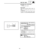
Reviews: