ELEC
8-1
ELECTRICAL
SWITCH INSPECTION
SWITCH INSPECTION
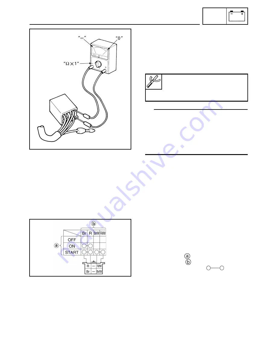
Use a analog pocket tester (pocket tester) to
check the terminals for continuity. If the conti-
nuity is faulty at any point, replace the switch.
TIP
• Set the analog pocket tester (pocket tester) to
“0” before starting a test.
• When testing the switch for continuity the
analog pocket tester (pocket tester) should be
set to the “
Ω
×
1” range.
• When checking the switch turn it on and off a
few times.
INSPECTING A SWITCH SHOWN IN THE
MANUAL
The terminal connections for switches (main
switch, handlebar switch, engine stop switch,
light switch, etc.) are shown in a chart similar
to the one on the left. This chart shows the
switch positions
in the column and the
switch lead colors
in the top row.
For each switch position, “
” indicates
the terminals with continuity.
The example chart shows that:
There is continuity between the brown and red
leads when the switch is set to “ON”.
There is continuity between the brown and red
and between the brown/white and red/white
leads when the switch is set to “START”.
Analog pocket tester:
YU-03112-C
Pocket tester:
90890-03112
SWITCH INSPECTION
Summary of Contents for Vector RS90GTZ
Page 1: ......
Page 74: ...INSP ADJ 2 51 Rear RST90GTZ Nipple Nipple both sides LUBRICATION ...
Page 329: ...FI 7 2 Passenger grip warmer relay RS90GTZ RS90LTGTZ RST90GTZ FUEL INJECTION SYSTEM ...
Page 330: ...FI 7 3 CIRCUIT DIAGRAM RS90GTZ RS90LTGTZ FUEL INJECTION SYSTEM ...
Page 332: ...FI 7 5 CIRCUIT DIAGRAM RST90GTZ FUEL INJECTION SYSTEM ...
Page 368: ...ELEC 8 2 IGNITION SYSTEM CIRCUIT DIAGRAM RS90GTZ RS90LTGTZ IGNITION SYSTEM ...
Page 370: ...ELEC 8 4 CIRCUIT DIAGRAM RST90GTZ IGNITION SYSTEM ...
Page 393: ...ELEC 8 27 CHARGING SYSTEM ...
Page 394: ...ELEC 8 28 LIGHTING SYSTEM CIRCUIT DIAGRAM RS90GTZ RS90LTGTZ LIGHTING SYSTEM ...
Page 396: ...ELEC 8 30 CIRCUIT DIAGRAM RST90GTZ LIGHTING SYSTEM ...
Page 404: ...ELEC 8 38 SIGNAL SYSTEM CIRCUIT DIAGRAM RS90GTZ RS90LTGTZ SIGNAL SYSTEM ...
Page 406: ...ELEC 8 40 CIRCUIT DIAGRAM RST90GTZ SIGNAL SYSTEM ...
Page 419: ...ELEC 8 53 SIGNAL SYSTEM ...
Page 420: ...ELEC 8 54 GRIP WARMER SYSTEM CIRCUIT DIAGRAM RS90GTZ RS90LTGTZ GRIP WARMER SYSTEM ...
Page 422: ...ELEC 8 56 CIRCUIT DIAGRAM RST90GTZ GRIP WARMER SYSTEM ...
Page 430: ...ELEC 8 64 COOLING SYSTEM CIRCUIT DIAGRAM RS90GTZ RS90LTGTZ COOLING SYSTEM ...
Page 458: ...SPEC 9 25 CABLE ROUTING CABLE ROUTING ...
Page 460: ...SPEC 9 27 CABLE ROUTING ...
Page 462: ...SPEC 9 29 RS90GTZ RS90LTGTZ CABLE ROUTING ...
Page 464: ...SPEC 9 31 RS90GTZ RS90LTGTZ CABLE ROUTING ...
Page 466: ...SPEC 9 33 RST90GTZ CABLE ROUTING ...
Page 468: ...SPEC 9 35 RST90GTZ CABLE ROUTING ...
Page 470: ...SPEC 9 37 RST90GTZ CABLE ROUTING ...
Page 472: ...SPEC 9 39 RS90GTZ RS90LTGTZ CABLE ROUTING ...
Page 474: ...SPEC 9 41 RS90GTZ RS90LTGTZ CABLE ROUTING ...
Page 476: ...SPEC 9 43 RST90GTZ CABLE ROUTING ...
Page 478: ...SPEC 9 45 RST90GTZ CABLE ROUTING ...
Page 480: ...SPEC 9 47 CABLE ROUTING ...
Page 482: ...SPEC 9 49 CABLE ROUTING ...
Page 484: ...SPEC 9 51 RS90GTZ RS90LTGTZ CABLE ROUTING ...
Page 486: ...SPEC 9 53 RST90GTZ CABLE ROUTING ...
Page 488: ...SPEC 9 55 RS90GTZ RS90LTGTZ CABLE ROUTING ...
Page 490: ...SPEC 9 57 RST90GTZ CABLE ROUTING ...
Page 492: ...SPEC 9 59 RST90GTZ CABLE ROUTING ...
Page 498: ......
Page 499: ......
Page 500: ......
Page 501: ...WIRING DIAGRAM 2010 RS90GTZ RS90LTGTZ 8JA 0F001 00 ...
Page 502: ...WIRING DIAGRAM 2010 RST90GTZ 8HF 0F001 00 ...
Page 503: ...WIRING DIAGRAM 2010 RS90GTZ RS90LTGTZ 8JA 0F001 00 ...


