background image

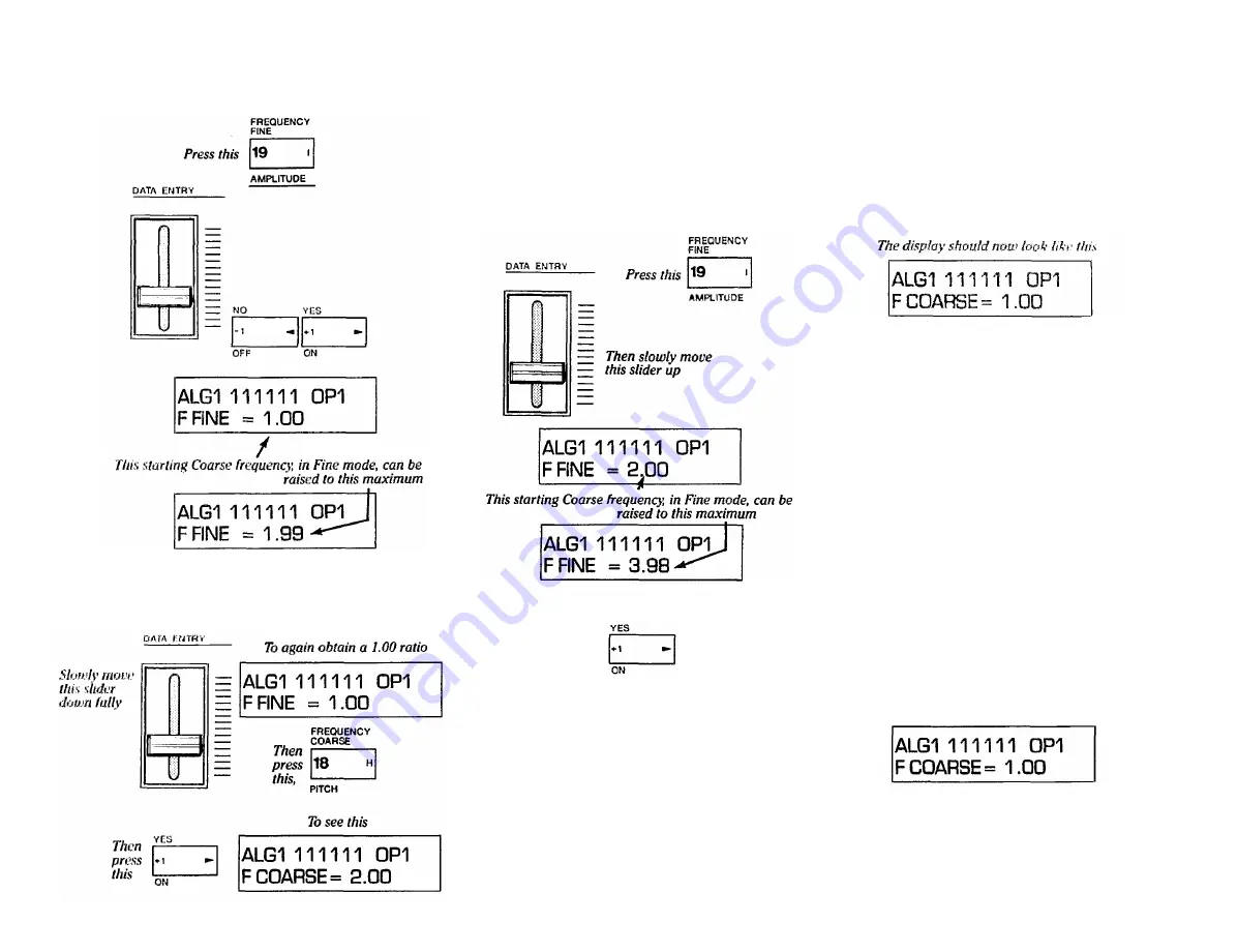
6. Slide [DATA ENTRY] all the way down so the fre-

quency returns to 1.00, and then press [OSCILLA-
TOR-FREQUENCY COARSE] and use DATA

ENTRY [+1] to set the frequency ratio to 2.00.

Then slowly move this slider

up and down fully, or use these

buttons while continuing to

play a note

7. Press [OSCILLATOR-FREQUENCY FINE] again,

and slowly move the (DATA ENTRY] slider all the
way up. The increments you get with the Fine adjust-

ment will depend on the beginning Coarse setting.

The pitch change will seem continuous when the

Fine adjustment is selected and you move the [DATA

ENTRY] slider, rather than discretely stepped, as it

does with the Coarse setting.

If the ratio does not quite reach 3.98 when you push the

slider up, press the increment button [>] once or more.

Notice the maximum increase available with the Fine

frequency adjustment is always a little less than twice

the beginning Coarse frequency The "Fine" control
multilplies the "Coarse" value by up to 1.99. For ex-

ample, if you start at a ratio of 1.00, the Fine adjust-
ment will go only as high as 1.99 (just under twice

1.00). Start at 2.00, and the Fine adjustment will go

only as high as 3.98. Start at 3.00, and the Fine ad-

justment will go only as high as 5.94. Start at 31.00,
and Fine will take you up to 61.69. Thus you can use
a combination of Coarse and Fine adjustments to
achieve anywhere from 1/2 the "normal" keyboard

pitch to nearly 62 times that frequency — which is

too high to be audible on all but the lowest notes of

the keyboard.

8. Slowly bring the [DATA ENTRY] slider all the way

down so the pitch returns to a ratio of 2.00. Then
press [OSCILLATOR-FREQUENCY COARSE] and
then the [-1] DATA ENTRY button to reset the ratio to

1.00. (This should now be identical to the "starting"

initialized voice.)

How to create Frequency Modulations
getting acquainted with the OPERATOR
SELECT, OUTPUT LEVEL and ON - OFF edit

featurec

Up to now you have manipulated only OPERATOR 1

which, in ALGORITHM 1, happens to be a carrier. We'll

now leave Operator 1 set at the "square" envelope at a

frequency ratio of 1.00 (as initialized), and begin ex-
ploring what happens when Operator 2 is used to mod-

ulate Operator 1. For review, we again point out the
Operator On/Off display (which you are about to use)

and illustrate Algorithm 1, but with additional informa-
tion you may now begin to understand.

NOTE If you 're "lost" or if it has been a while since

you read and followed the instructions in the previous

sections, you can start "from scratch" here by pressing
[FUNCTION], then [VOICE INIT], then answering

[YES] [YES]. The DX7 will now be set as we assume

it is for the following instructions. The display how-

ever, may not match: if a different editing parameter is
shown, press
 [OSCILLATOR-FREQUENCY

COARSE]. Now your diplay should match the follow-

ing illustration.

Remember the display of 6 1 's tell you the correspond-

ing 6 operators are turned ON at this point in the pro-

gramming process. The On/Off "switches" are shown in

the following algorithm diagram.

33

Summary of Contents for Vintage DX7 Special Edition ROM

Page 1: ...YAMAHA AUTHORIZED PRODUCT MANUAL DX7 DIGITALPROGRAMMABLE ALGORITHMSYNTHESIZER...

Page 2: ...YAMAHA DigitalProgrammable Algorithm Synthesizer OPERATION MANUAL...

Page 3: ...oth and dry with a soft cloth Never use solvents such as benzine or thin ner since they can melt or discolor the instrument Electrical Storms Lightning Computer circuitry including that in the DX7 is...

Page 4: ...u program them with the preci sion and repeatability of digital control you ll be able to create voices that are a giant step beyond the capability of former synthesizers Pure sounds Richly textured s...

Page 5: ......

Page 6: ...ument does indeed appear to be the source of the interference one or more of the following corrective measures should be tried 1 Relocate either the instrument or the electronic device that is being a...

Page 7: ...ALGORITHMSELECT KEYBOARD RATE SCALING and LEVEL SCALING 38 LFO Modulation The relationship between the LFO settingsandthe MODSENSITIVITY settings and how to program these 40 Programming the remaining...

Page 8: ...ks like this OPERATOR ON OFF 1 The same button used in context b is described like this EG COPY 1 When the DX7 is in the FUNCTION mode rather than the EDIT mode the brown label below it applies instea...

Page 9: ...tors These jacks include the line level output from the DX7 to an amplifier foot control jacks and MIDI interface connections Refer to the Setup and MIDI sections of this manual for details Volume and...

Page 10: ...of these buttons prepares the DX7 to PLAY any of the voices that are stored in the 32 INTER NAL memories or in 32 memories of whatever CAR TRIDGEisinstalled Oncethe INTERNAL or CARTRIDGE source is des...

Page 11: ...en it is used to change the amplitude of a carrier tremolo may result changing the amplitude of a modulator can create wah wah WAVE This lets you set the LFO waveform to any of the following triangle...

Page 12: ...rammable with each button and the range of adjustment is from the minimum of 0 to a maximum of 99 100 steps RATE Pressing this button 4 successive times gives you access to programming the 4 rates in...

Page 13: ...ally refer to frequency excursions The Pitch EG can be used for automatic pitch bending effects including the slight pitch changes that occur with plucked strings However the 8 octave range of this fe...

Page 14: ...nal note or chord GLISSANDO When the Glissando feature is turned ON the glide in pitch occurs in discrete steps This effect is best heard with a slower rate and when two widely sepa rated notes are pl...

Page 15: ...settings NOTE ifthe Amplitude or EG Bias is turned On with a low Range setting certain voices may be inaudible or nearly so due to their high modulation sensitivity RANGE This lets you program the am...

Page 16: ...us or minus one octave The smoothness depends on the PITCH BEND STEP setting 11 Modulation Wheel The Modulation wheel permits you to introduce LFO modulation of pitch and or amplitude and or EG bias a...

Page 17: ...ne plug None of these jacks needs to be used for normal opera tion of the DX7 but if the foot controllers are used be sure you plug in the proper type of controller The picto rial diagrams on the rear...

Page 18: ...uitar type cable and connect the center conductor to XLR s hot pin Then wire the shield to the other two pins of the XLR if hum is a problem cut the shield connection to pin 1 ofthe XLR The nominal ou...

Page 19: ...at voice name will appear The LCD display INT 1 is really redundant here it tells you that internal voice 1 is selected which you can read from the top line of the LCD window and the red LED voice num...

Page 20: ...CARTRIDGE button has already been pressed and the top line of the LCD display already indi cates CARTRIDGE VOICE ifnot do so now There fore you should only have to press the 8 button Press this The d...

Page 21: ...narrow range 75 cents we make it easier to tune precisely with the slider However since each voice can itself be programmed to a unique pitch or can be easily transposed as explained elsewhere there i...

Page 22: ...of these When the DX7 is set for a pitch bend range ofplus or minus an octave the display should look like this 3 Notice that if you hold a key and hold the PITCH wheel at a given position moving the...

Page 23: ...KEY P RETAIN Then ifnecessary movethe slider downor press this but tonso thedisplay indicates SUS KEY P RETAIN 4 Now play several notes one after the other while stepping on the SUSTAIN pedal Play a b...

Page 24: ...NO andthentheDATAENTRY button 3 Select the Fingered Portamento mode by pressing PORTAMENTO MODE and then the DATA ENTRY button 4 Observe that if you hold down one key then press a second key that is a...

Page 25: ...them to a DX9 once SYS INFO AVAIL is displayed press the MIDI button 8 again and when the display asks MIDI TRANSIT press the YES but ton memory protect must be OFF in the other synthe sizer Individua...

Page 26: ...just one modulation source the MODULATION WHEEL First make sure all modulation is OFF NOTE While you may not be using a given source of modulation it can still affect the voice ifits FUNC TION control...

Page 27: ...WHEEL RANGE 99 leave these controls set and try other voices Other voices may be programmed to be sensi tive to pitch modulation From this point you can access other voices by press ing MEMORY SELECT...

Page 28: ...OFF EG BIAS OFF OFF OFF OFF These settings are not ideal for all voices If for in stance you re playing the voice called SAX BC1 you will want to turn ON the Breath Controller EG bias and perhaps set...

Page 29: ...stack the car rier and any operators that are above and which feed its input are known as modulators By increasing the output level of the modulators going into a given the carrier you increase the nu...

Page 30: ...CK path The feedback is usually wrapped around a single operator with a few exceptions noted below The feed back returns a portion of the operators output back to an additional input on the same opera...

Page 31: ...ze the line defined by R1 and L1 as the attack portion of the envelope There are parallels between a conventional ADSR EGs and the DX7 s EGs However the DX7 envelopes are much more flexible than ADSR...

Page 32: ...nd gain a working knowledge of envelopes frequency ratios keyboard scaling and so forth you ll find creating a voice from scratch will become much easier and editing an exist ing voice a preset or one...

Page 33: ...changes when you play a note In the initialized voice all the operator s EG are set to produce an envelope with a square shape That is when you press a key to play a note the operator the sine wave ca...

Page 34: ...OP1 EG LEVEL 4 0 4 Lets look at the 4 envelope rates Press the EG RATE button and the display will now show you Rate 1 Press it 3 additional times to see the remain ing 3 rates Both EG Rate and EG Lev...

Page 35: ...the last portion of a long release time With all maximum levels at 99 except Level 4 Rate 1 at 25 and Rate 4 at 25 the note builds up slowly when you press a key and turns off even more slowly when yo...

Page 36: ...t at zero In fact Rate 4 sets the release time from whatever levelthe envelope has achieved at the instant you release the key This may seem a subtle distinction but you can hear it by experimenting w...

Page 37: ...amming dog whis tles or ultrasonic alarm simulations you won t ever use a ratio near 31 00 as a funda mental pitch tor a carrier NOTE The pitches you hear as you move the DATA ENTRY slider constitute...

Page 38: ...2 times that frequency which is too high to be audible on all but the lowest notes of the keyboard 8 Slowly bring the DATA ENTRY slider all the way down so the pitch returns to a ratio of 2 00 Then pr...

Page 39: ...or that is set as the current operator 3 Now press OPERATOR SELECT several times and observe that the display only moves between OP1 and OP2 Leave it set to OP2 34 Theheavy lineshowswhichoperatorscont...

Page 40: ...raise it or use the 1 and 1 buttons while playing Only the frequency should change in the display From a minimum of 0 50 to a maximum of 31 00 Listen to each ratio You are changing the entire harmonic...

Page 41: ...only be set to an operator that is on And see the display change to this Note the current operator stays at OP1 If you again want to adjust any parameters for Operator 2 you will have to press the OP...

Page 42: ...e to become pure when you release the key We ll correct that situation next There is no need to change the EG levels for now Operator1levels remain unchanged Initialized levels forOperator1 EG LEVEL 1...

Page 43: ...NOTE These instructions assume you have followed the instructions in the previous section and that the DX7 is in the EDIT mode Before you go on the dis play should appear as shown here and Operators 1...

Page 44: ...but instead changes the rates for each group of 3 keys on the keyboard When you ve tried the maximum reset the scaling to a value of 4 And push up DATA ENTRY leave it set like this In this case the ra...

Page 45: ...the DATA ENTRY controls to see this Now play up the scale from E4 and hear how you have removed just a bit of volume from the highest notes NOTE In the examplesjust given the keyboard level scaling ma...

Page 46: ...be greater than zero Lets program a small amount of sine wave modula tion of the pitch to give the sound some character 1 Press the WAVE button You can now use the DATA ENTRY section to select any of...

Page 47: ...LFO section to automatically add a small amount of vibrato to the voice simulating the natural vibrato in a reed instrument However the effect is there all the time whereas in a real instru ment the v...

Page 48: ...fect And adjust the DATA ENTRY controls to see this 13 Press MOD SENSITIVITY AMPLITUDE and then press OPERATOR SELECT to set Operator 2 as the current operator Then use DATA ENTRY to bring up the sens...

Page 49: ...maximum level R1 L1 for the hammer strike followed by a slow fall to an inter mediate decay level R2 L2 which has the effect of widening the hammer strike and making less of a click There is no susta...

Page 50: ...e operators 3 4 5 6 16 Press OPERATOR SELECT as many times as needed to set operator 3 as current Then press OSCILLATOR FREQUENCY COARSE and you ll see the ratio is now set at 2 00 To transpose an oct...

Page 51: ...CTION button to place the DX7 in FUNCTIONmode b Press the EDIT RECALL button then press the DATA ENTRY YES button to answer the two prompts edit recall and are you sure c You have now recovered the lo...

Page 52: ...to compare the newly edited sound to the original sound you can press the EDIT COMPARE button once Notice the decimal point in the LED voice number display disappears and the number itself begins to...

Page 53: ...ana lyze and record the parameters of several preset voices strictly as a learning tool for you Play the voices look at the way the voice is programmed and try to understand how the settings affect t...

Page 54: ...voice The LCD display will briefly indicate Under Writing and will then return to the voice name and number indicating the voice has been stored NOTE Ifyou attempt this step with either the software...

Page 55: ...voice you want to move and then press STORE and the voice selector of the memory in which you wish to store this voice 3b If you want to move the voice into the same or a dif ferent position within th...

Page 56: ...d be worthwhile to reprogram the attack rate or to add some Keyboard Rate Scaling if the problem is pri marily at the upper end of the keyboard All of the preceding suggestions may be completely inapp...

Page 57: ...ture Regardless of the algorithm you select use the fewest number of operators you can when you begin to pro gram Turn off the others while programming by using the OPERATOR ON OFF buttons ifyou want...

Page 58: ...low hard into the BC 1 the level comes back up to the maximum level permitted by the enve lope at any given instant you must have played the note first on the keyboard so that the EG bias is bringing...

Page 59: ...er or ON and OFF buttons will toggle the keyboard between polyphonic and mono operation 5 Press MEMORY SELECT internal or cartridge to enter the PLAY mode When you select a voice like the Fretless Bas...

Page 60: ...voice assignments For example moving the Mas ter s MODULATION Wheel to full forward deflection might cause a slight bit of LFO pitch modulation on that instrument while on the Slave there might be a...

Page 61: ...e you press a voice selec tor buttons 1 32 both instruments will go to that numbered voice memory Both will play and will respond to modulation controls if the FUNCTION mode programming is appropriate...

Page 62: ...IT mode information from 1 voice on the Master and apply it to another voice on the Slave As soon as you select or alter any EDIT parameter on the Master that value change is auto matically transmitte...

Page 63: ...e selected a voice which has a lot of amplitude modulation sensitivity programmed into its carriers and that one of the modu lation controls is programmed with a significant amount of amplitude modula...

Page 64: ...rned off due to an internal battery The other voice storage medium is the cartridge There are two types of cartridges RAM and ROM see thesedefinitions Cartridge Form This is an abbreviation for cartri...

Page 65: ...contain some data some numbers that describe a voice If all data were set to zero you would hear nothing and it would take a lot of programming to get any sound at all Therefore when you INITialize th...

Page 66: ...vided the MODULATION SENSITIVITY PITCH setting is greater than zero Preset A preset is a voice which can be played without having to be programmed Some synthesizers force the player to program any voi...

Page 67: ...Sustain Key Pitch Retain See Key Pitch Retain Sustain In a synthesizer the sustain describes the level which a note settles into while a key is held down or while the sustain foot pedal is pressed do...

Page 68: ...PITCH BEND RANGE STEP PORTAMENTO MODE POLY MONO GLISSANDO TIME MODULATION WHEEL RANGE PITCH AMPLITUDE EG BIAS FOOT CONTROL RANGE PITCH AMPLITUDE EG BIAS BREATH CONTROL RANGE PITCH AMPLITUDE EG BIAS AF...

Page 69: ...yboardratescaling 8 38 39 46 51 59 63 key sync see sync LCD C 3 5 6 14 16 18 21 22 47 49 56 58 60 63 LFO includes LFO AMD delay modulation PMD speed sync wave 6 7 10 11 21 22 40 43 51 56 59 63 load C...

Page 70: ...YAMAHA VOICE DATA LIST...

Page 71: ...DX7 OM 5 20 99 19E0112 international Corp Box 6600 Buena Park Calif 90622...

Page 72: ...YAMAHA Yamaha Corporation of America 6600 Orangethorpe Avenue P O Box 6600 Buena Park CA 90622 6600 10 11 99 19J0062 DX7 OM...

Reviews: