4 - 14
ENG
CAMSHAFTS
EAS00218
INSTALLING THE CAMSHAFTS
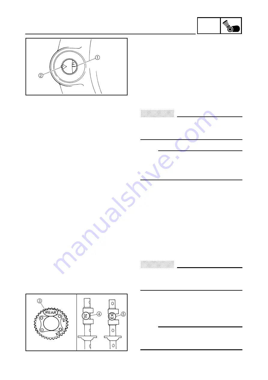
1. Align:
• “T1” marks on the flywheel
(with the stationary pointer on the crank-
case cover)
▼▼▼▼▼▼▼▼▼▼▼▼▼▼▼▼▼▼▼▼▼▼▼▼▼▼▼▼▼▼▼
a. Turn the crankshaft counterclockwise.
b. When piston #1 is at TDC on the compres-
sion stroke, align the “T1” marks
1
on the
generator rotor with the stationary pointer
2
.
CAUTION:
@
Do not turn the crankshaft when installing
the camshaft to avoid damage or improper
valve timing.
@
NOTE:
@
First, install the rear cylinder camshafts, cam-
shaft sprockets, timing chain, and timing chain
tensioner. Then, install the front cylinder cam-
shafts and related parts.
@
▲▲▲▲▲▲▲▲▲▲▲▲▲▲▲▲▲▲▲▲▲▲▲▲▲▲▲▲▲▲▲
Rear cylinder
1. Install:
• intake camshaft
• exhaust camshaft
▼▼▼▼▼▼▼▼▼▼▼▼▼▼▼▼▼▼▼▼▼▼▼▼▼▼▼▼▼▼▼
CAUTION:
@
Do not turn the crankshaft when installing
the camshafts to avoid damage or improper
valve timing.
@
a. Install the camshaft sprockets onto the
camshafts.
Refer to the camshaft sprocket installation
steps below.
NOTE:
@
Make sure the “REAR” marks
3
on the cam-
shaft sprockets face away from the “IN”
4
and
“EX” marks
5
on the camshafts.
@
Summary of Contents for VMX12 2001
Page 1: ...VMX12 2001 3LRD AE1 SERVICEMANUAL ...
Page 2: ......
Page 8: ......
Page 9: ...GEN INFO 1 ...
Page 11: ...GEN INFO ...
Page 21: ......
Page 22: ...SPEC 2 ...
Page 24: ...SPEC ...
Page 52: ...2 28 SPEC OIL FLOW DIAGRAMS 1 Camshaft 2 Main gallery 3 Crankshaft 4 Oil level switch ...
Page 54: ...2 30 SPEC OIL FLOW DIAGRAMS 1 Crankshaft 2 Oil pipe 3 Oil filter ...
Page 65: ...CHK ADJ 3 ...
Page 125: ......
Page 126: ...ENG 4 ...
Page 130: ...ENG ...
Page 236: ......
Page 237: ...COOL 5 ...
Page 239: ...COOL ...
Page 258: ...CARB 6 ...
Page 260: ...CARB ...
Page 272: ......
Page 273: ...CHAS 7 ...
Page 389: ......
Page 390: ...ELEC 8 ...
Page 396: ...8 4 ELEC SWITCHES ...
Page 417: ...8 25 ELEC STARTER MOTOR 3 Install O rings 1 bolts 2 New T R 5 Nm 0 5 m kg ...
Page 445: ...TRBL SHTG 9 ...


