4 - 81
ENG
CONNECTING RODS AND PISTONS
NOTE:
@
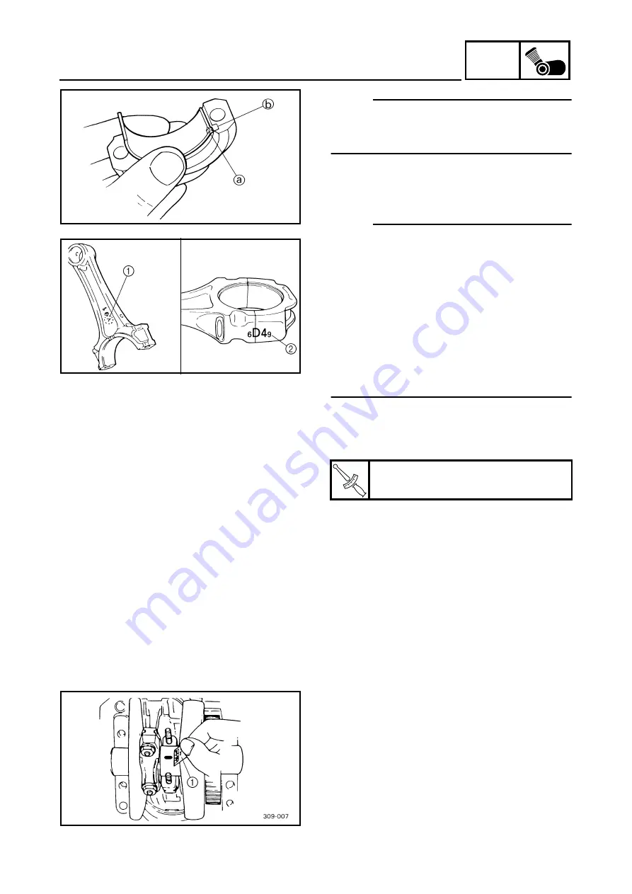
Align the projections
a
on the big end bear-
ings with the notches
b
in the connecting rod
and connecting rod cap.
@
c. Put a piece of Plastigauge
®
on the crank-
shaft pin.
d. Assemble the connecting rod halves.
NOTE:
@
• Do not move the connecting rod or crank-
shaft until the clearance measurement has
been completed.
• Lubricate the bolts threads and nut seats
with molybdenum disulfide grease.
• Make sure the “Y” mark
1
on the connecting
rod faces towards the left side of the crank-
shaft.
• Make sure the characters
2
on both the con-
necting rod and connecting rod cap are
aligned.
@
e. Tighten the connecting rod nuts.
Refer to “INSTALLING THE PISTONS AND
CYLINDERS”.
f. Remove the connecting rod and big end
bearings.
Refer to “REMOVING THE CONNECTING
RODS AND PISTONS”.
T
R
.
.
Connecting rod nut
36 Nm (3.6 m • kg)
g. Measure the compressed Plastigauge
®
width
1
on the crankshaft pin. If the crank-
shaft-pin-to-big-end-bearing clearance is
out of specification, select replacement big
end bearings.
▲▲▲▲▲▲▲▲▲▲▲▲▲▲▲▲▲▲▲▲▲▲▲▲▲▲▲▲▲▲▲
Summary of Contents for VMX12 2001
Page 1: ...VMX12 2001 3LRD AE1 SERVICEMANUAL ...
Page 2: ......
Page 8: ......
Page 9: ...GEN INFO 1 ...
Page 11: ...GEN INFO ...
Page 21: ......
Page 22: ...SPEC 2 ...
Page 24: ...SPEC ...
Page 52: ...2 28 SPEC OIL FLOW DIAGRAMS 1 Camshaft 2 Main gallery 3 Crankshaft 4 Oil level switch ...
Page 54: ...2 30 SPEC OIL FLOW DIAGRAMS 1 Crankshaft 2 Oil pipe 3 Oil filter ...
Page 65: ...CHK ADJ 3 ...
Page 125: ......
Page 126: ...ENG 4 ...
Page 130: ...ENG ...
Page 236: ......
Page 237: ...COOL 5 ...
Page 239: ...COOL ...
Page 258: ...CARB 6 ...
Page 260: ...CARB ...
Page 272: ......
Page 273: ...CHAS 7 ...
Page 389: ......
Page 390: ...ELEC 8 ...
Page 396: ...8 4 ELEC SWITCHES ...
Page 417: ...8 25 ELEC STARTER MOTOR 3 Install O rings 1 bolts 2 New T R 5 Nm 0 5 m kg ...
Page 445: ...TRBL SHTG 9 ...


