ENGINE REMOVAL
ENGINE
OVERHAUL
ENGINE REMOVAL
\
NOTE:
It
is not necessary to remove the engine in
order t o remove the following components:
.Clutch
Carburetor
pump
magneto
PREPARATION FOR REMOVAL
Remove
all dirt, mud, dust, and foreign
material before removal and disassembly.
Use proper tools and cleaning equipment.
Refer to "CHAPTER
1.
SPECIAL TOOL"
section.
NOTE:
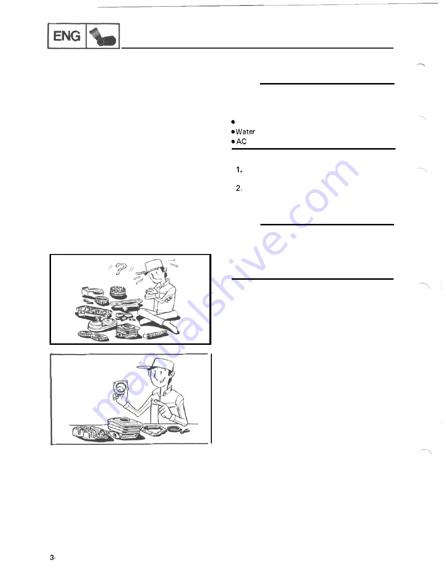
When disassembling the engine, keep mated parts
together. This includes gears, cylinders, pistons,
and other parts that have been "mated" through
normal wear. Mated parts must be reused as an
assembly or replaced.
3.
During engine disassembly, clean all parts
and place them in trays in the order of
disassembly. This will speed up assembly
time and help assure that all parts are
correctly reinstalled in the engine.
4. Drain engine oil completely.
Refer to "CHAPTER
2. ENGINE OIL
REPLACEMENT" section.
5. Drain coolant completely.
Refer t o "CHAPTER
4. COOLANT
RE-
PLACEM
ENT" section.
1
Summary of Contents for VMX12H
Page 1: ...VMXl2N NC K KC...
Page 2: ...LIT 11616 10 12...
Page 22: ...VAMAHA MOTOR CO LTD PRINTEDI N U S A...
Page 23: ...E LIT 11616 08 77...
Page 44: ...CIRCUIT DIAGRAM ELECTRICAL CIRCUIT DIAGRAM I I 1...
Page 48: ...VAMAHA MOTOR CO LTD PRINTED IN U S A...
Page 49: ...I LIT I1616 06 08...
Page 56: ...TO IWATA JAPAN PRINTED IN U S A...
Page 57: ...LIT 1...
Page 64: ...IWATA JAPAN PRINTED IN U S A...
Page 65: ...I Serr ice L 1616 04 67...
Page 206: ...ENGINE ASSEMBLY AND ADJUSTMENT MEMO 3 82...
Page 304: ...CIRCUIT DIAGRAM I I ELECTRICAL CIRCUIT DIAGRAM w w 7 1...
Page 308: ...ELECTRIC STARTING SYSTEM I I ELECTRIC STARTING SYSTEM CIRCUIT DIAGRAM 7 5...
Page 320: ...CHARGING SYSTEM CHARGING SYSTEM CIRCUIT DIAGRAM 7 17...
Page 325: ...MEMO 7 22...
Page 326: ...IGNITION SYSTEM IGNITION SYSTEM CIRCUIT DIAGRAM 7 23...
Page 334: ...LIGHTING SYSTEM LIGHTING SYSTEM CIRCUIT DIAGRAM 7 31...
Page 339: ...MEMO 7 36...
Page 340: ...SIGNAL SYSTEM SIGNAL SYSTEM CIRCUIT DIAGRAM 7 37...
Page 348: ...COOLING SYSTEM COOLING SYSTEM CIRCUIT DIAGRAM 7 45...
Page 354: ...FUEL PUMP SYSTEM FUEL PUMP SYSTEM CIRCUIT DIAGRAM 7 51...
Page 362: ...V BO O ST SYSTEM V BO O ST SYSTEM CI RCUI T DI AG RAM...
Page 390: ...LUBRICATION DIAGRAMS LUBRICATION AGRAMS LUBRICATION DIAGRAM 8 20...
Page 391: ...LUBRICATION DIAGRAMS LUBRICATION DIAGRAM 2 8 21...
Page 392: ...LUBRICATION AGRAMS LUBRICATION DIAGRAM 8 22...
Page 393: ...LUBRICATION DIAGRAMS LUBRICATION DIAGRAM 4...
Page 401: ...CABLE ROUTING CANISTER PIPE ROUTING To carburetor To fuel tank TO Canister...
Page 403: ...m...


