M ID D LE G EA R SER VIC E
E xam ple: S election of the drive pinion gear
shim ;
Shim Thickness =
D istance “A ” -
D istance “B ”
If the drive pinion gear is stam ped “03” (plus
(+ 03) is im plied here since only the m inus
(-) designations are stam ped alongside the
num bers), then:
“A” = 53 -- 0.03
= 54.53
N O TE:
A ll stam ped num bers are in hundredths of a
m m .
If the left-side-rear of the upper crankcase
is stam ped
then:
= 53 + 0.95
= 53.95
Therefore:
T = A - B
54.53 53.95
= 0.58 m m
calculated shim thickness is 0.58 m m .
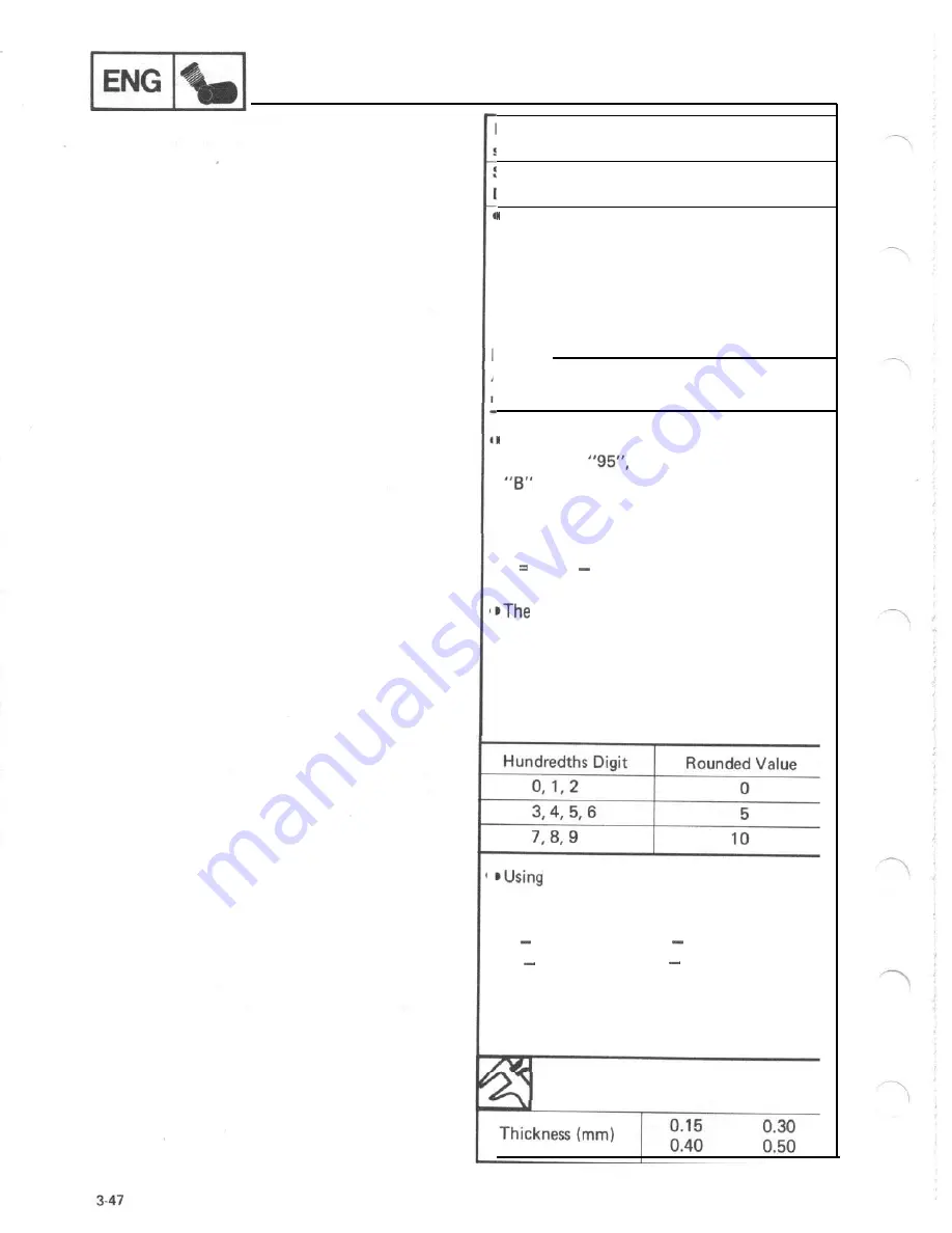
Because shim can only be selected in 0.05
m m increm ents, use the follow ing chart to
round off the hundredths digit of the calcu-
lated thickness and selest the appropriate
shim ,
the above exam ple, the calculated
shim thickness of 0.58 m m is rounded off to
0.60 m m . Therefore, you m ay choose either
4
0.15 m m shim s, 2 0.30 m m shim s, or
1
0.30 m m and 2
0.15 m m shim s as
selected from the shim thickness chart
below . Shim size are supplied in the follow -
ing thicknesses:
D rive Pinion G ear Shim
Summary of Contents for VMX12H
Page 1: ...VMXl2N NC K KC...
Page 2: ...LIT 11616 10 12...
Page 22: ...VAMAHA MOTOR CO LTD PRINTEDI N U S A...
Page 23: ...E LIT 11616 08 77...
Page 44: ...CIRCUIT DIAGRAM ELECTRICAL CIRCUIT DIAGRAM I I 1...
Page 48: ...VAMAHA MOTOR CO LTD PRINTED IN U S A...
Page 49: ...I LIT I1616 06 08...
Page 56: ...TO IWATA JAPAN PRINTED IN U S A...
Page 57: ...LIT 1...
Page 64: ...IWATA JAPAN PRINTED IN U S A...
Page 65: ...I Serr ice L 1616 04 67...
Page 206: ...ENGINE ASSEMBLY AND ADJUSTMENT MEMO 3 82...
Page 304: ...CIRCUIT DIAGRAM I I ELECTRICAL CIRCUIT DIAGRAM w w 7 1...
Page 308: ...ELECTRIC STARTING SYSTEM I I ELECTRIC STARTING SYSTEM CIRCUIT DIAGRAM 7 5...
Page 320: ...CHARGING SYSTEM CHARGING SYSTEM CIRCUIT DIAGRAM 7 17...
Page 325: ...MEMO 7 22...
Page 326: ...IGNITION SYSTEM IGNITION SYSTEM CIRCUIT DIAGRAM 7 23...
Page 334: ...LIGHTING SYSTEM LIGHTING SYSTEM CIRCUIT DIAGRAM 7 31...
Page 339: ...MEMO 7 36...
Page 340: ...SIGNAL SYSTEM SIGNAL SYSTEM CIRCUIT DIAGRAM 7 37...
Page 348: ...COOLING SYSTEM COOLING SYSTEM CIRCUIT DIAGRAM 7 45...
Page 354: ...FUEL PUMP SYSTEM FUEL PUMP SYSTEM CIRCUIT DIAGRAM 7 51...
Page 362: ...V BO O ST SYSTEM V BO O ST SYSTEM CI RCUI T DI AG RAM...
Page 390: ...LUBRICATION DIAGRAMS LUBRICATION AGRAMS LUBRICATION DIAGRAM 8 20...
Page 391: ...LUBRICATION DIAGRAMS LUBRICATION DIAGRAM 2 8 21...
Page 392: ...LUBRICATION AGRAMS LUBRICATION DIAGRAM 8 22...
Page 393: ...LUBRICATION DIAGRAMS LUBRICATION DIAGRAM 4...
Page 401: ...CABLE ROUTING CANISTER PIPE ROUTING To carburetor To fuel tank TO Canister...
Page 403: ...m...


