B A T T E R Y INSPECTION
1.
Inspect:
Refer
to "CHAPTER
2
B A T T E R Y IN-
SPECTION" section.
STARTER R E L A Y TEST
.
.
,
1.
Inspect:
realy
Poor condition
Replace.
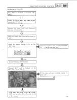
B y the following inspection steps.
Starter relay inspection steps:
the seat.
ignition switch to
"ON",
engine stop
switch to " RUN"and
shift pedal to
R
A L".
the starter motor lead
from
the starter motor.
the starter switch and check to see
if
the starter relay clicks.
Starter relay clicking
Starter relay
OK.
Starter relay not clicking
Measure coil
resistance.
2.
Measure:
relay resistance
O u t of specification
Replace.
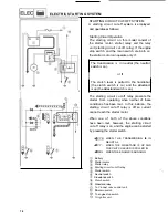
B y the following measurement steps.
Starter relay resistance measurement steps:
.Disconnect the
lead and the battery
the Pocket Tester
leads
Red
the coil resistance.
positive lead.
to
the starter relay.
Starter Relay Resistance:
3.5
10%
at 20°C
(68°F)
the resistance is not within specification,
replace the starter relay.
7-13
Summary of Contents for VMX12H
Page 1: ...VMXl2N NC K KC...
Page 2: ...LIT 11616 10 12...
Page 22: ...VAMAHA MOTOR CO LTD PRINTEDI N U S A...
Page 23: ...E LIT 11616 08 77...
Page 44: ...CIRCUIT DIAGRAM ELECTRICAL CIRCUIT DIAGRAM I I 1...
Page 48: ...VAMAHA MOTOR CO LTD PRINTED IN U S A...
Page 49: ...I LIT I1616 06 08...
Page 56: ...TO IWATA JAPAN PRINTED IN U S A...
Page 57: ...LIT 1...
Page 64: ...IWATA JAPAN PRINTED IN U S A...
Page 65: ...I Serr ice L 1616 04 67...
Page 206: ...ENGINE ASSEMBLY AND ADJUSTMENT MEMO 3 82...
Page 304: ...CIRCUIT DIAGRAM I I ELECTRICAL CIRCUIT DIAGRAM w w 7 1...
Page 308: ...ELECTRIC STARTING SYSTEM I I ELECTRIC STARTING SYSTEM CIRCUIT DIAGRAM 7 5...
Page 320: ...CHARGING SYSTEM CHARGING SYSTEM CIRCUIT DIAGRAM 7 17...
Page 325: ...MEMO 7 22...
Page 326: ...IGNITION SYSTEM IGNITION SYSTEM CIRCUIT DIAGRAM 7 23...
Page 334: ...LIGHTING SYSTEM LIGHTING SYSTEM CIRCUIT DIAGRAM 7 31...
Page 339: ...MEMO 7 36...
Page 340: ...SIGNAL SYSTEM SIGNAL SYSTEM CIRCUIT DIAGRAM 7 37...
Page 348: ...COOLING SYSTEM COOLING SYSTEM CIRCUIT DIAGRAM 7 45...
Page 354: ...FUEL PUMP SYSTEM FUEL PUMP SYSTEM CIRCUIT DIAGRAM 7 51...
Page 362: ...V BO O ST SYSTEM V BO O ST SYSTEM CI RCUI T DI AG RAM...
Page 390: ...LUBRICATION DIAGRAMS LUBRICATION AGRAMS LUBRICATION DIAGRAM 8 20...
Page 391: ...LUBRICATION DIAGRAMS LUBRICATION DIAGRAM 2 8 21...
Page 392: ...LUBRICATION AGRAMS LUBRICATION DIAGRAM 8 22...
Page 393: ...LUBRICATION DIAGRAMS LUBRICATION DIAGRAM 4...
Page 401: ...CABLE ROUTING CANISTER PIPE ROUTING To carburetor To fuel tank TO Canister...
Page 403: ...m...


