3 - 13
BASICS
Chapter 3
Learning the Basics
Scenes
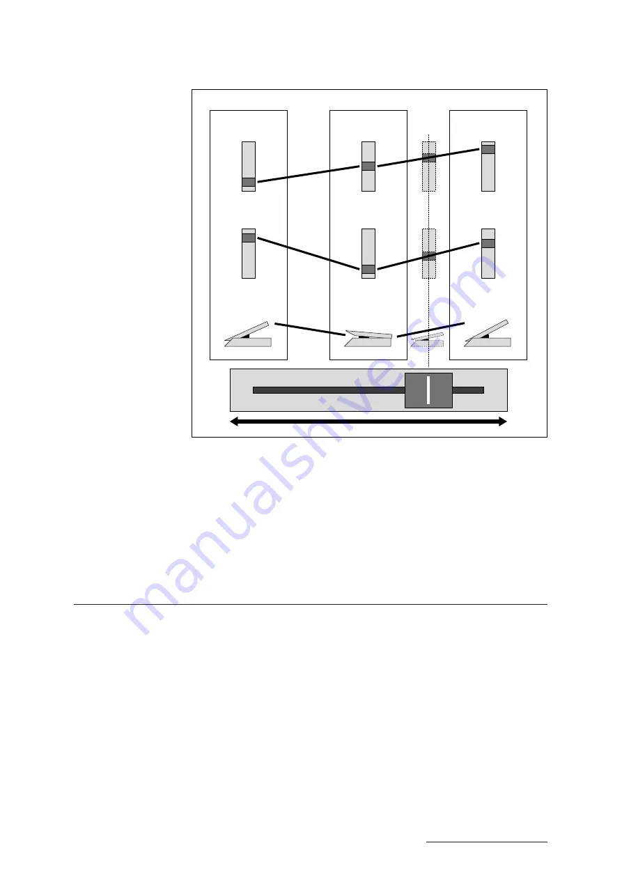
You can use a foot controller to obtain the same control you get with the SCENE
CONTROLLER knob. Simply connect the foot controller into the SCENE jack on the
VP1’s rear panel. The foot controller’s highest position corresponds to Scene 1; the
fully depressed position corresponds to Scene 3.
Note also that you can use the SYSTEM mode’s “Aftertouch Scene” switch to select
whether or not the scene controller operates on aftertouch data. (
➝
REFERENCE: 2-
4)
Scene LEDs
The LED above each SCENE button indicates how “close” you are to that scene. You
can see how this works by watching the LEDs as you move the SCENE
CONTROLLER up and back.
Red:
At the scene
Yellow:
Close to the scene
Green:
Moving away from the scene
Off:
Far from the scene
MODULATION
1 wheel
MODULATION
1 wheel
MODULATION
1 wheel
MODULATION
2 wheel
MODULATION
2 wheel
MODULATION
2 wheel
Foot
controller 1
Foot
controller 1
Foot
controller 1
Scene 1
Scene 2
Scene 3
SCENE CONTROLLER
Summary of Contents for VP1
Page 1: ......
Page 12: ...BASICS PART...
Page 69: ...REFERENCE PART...
Page 151: ...App 1 REFERENCE Appendix Appendix...
Page 171: ...Index 1 VP1 OWNER S MANUAL Index...


