5-111
E
POWR
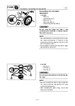
Connecting rod and piston
installation
1. Install:
•
Piston
1
•
Connecting rod
2
•
Piston pin
3
•
Piston pin clips
4
•
Connecting rod cap bolts
5
CAUTION:
Do not reuse the piston pin clips
4
and
connecting rod cap bolts
5
, always replace
them with new ones.
NOTE:
•
When installing the connecting rod to the pis-
ton, make sure that the
“
Y
”
mark
a
on the
connecting rod faces towards the front mark
b
on the piston crown.
•
Do not allow the piston pin clip ends to align
with the piston pin slot
c
.
M
1
4
c
4
3
b
5
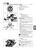
2. Install:
•
Oil ring
1
•
2nd ring
2
•
Top ring
3
CAUTION:
Do not scratch the pistons or break the pis-
ton rings.
NOTE:
•
Be sure to install the piston rings so that the
“
1T
”
mark on the top ring and the
“
2T
”
mark
on the 2nd ring face up.
•
After installing the piston rings, check that
they move smoothly.
1T
2T
3
1
2
E
E
Summary of Contents for WaveRunner FX SHO
Page 1: ...SERVICE MANUAL FX SHO WaveRunner F1W 28197 1K 11 FX Cruiser SHO LIT 18616 03 12 LIT186160312 ...
Page 58: ...1 53 E GEN INFO MEMO Technical tips ...
Page 82: ...2 23 E SPEC MEMO Cable and hose routing ...
Page 110: ...3 27 E CHK ADJ MEMO General ...
Page 243: ...5 118 E POWR 1 2 3 4 5 6 7 8 9 MEMO Cooling water ...
Page 275: ...6 30 E JET PUMP 1 2 3 4 5 6 7 8 9 MEMO Intermediate housing ...
Page 353: ...E ELEC 1 2 3 4 5 6 7 8 9 7 76 MEMO Indication system ...
Page 410: ...8 55 E HULL HOOD MEMO Deck and hull ...
Page 429: ...9 18 E TRBL ANLS 1 2 3 4 5 6 7 8 9 MEMO Engine unit trouble analysis ...
Page 431: ......
Page 432: ...YAMAHA MOTOR CORPORATION USA Printed in USA Jan 2008 0 0 1 CR E ...


