6-16
E
JET
PUMP
BEARING HOUSING
BEARING HOUSING
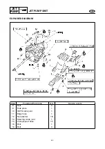
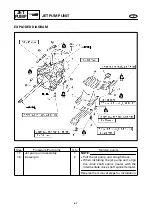
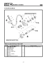
EXPLODED DIAGRAM
REMOVAL AND INSTALLATION CHART
Step
Procedure/Part name
Q’ty
Service points
BEARING HOUSING REMOVAL
Follow the left “Step” for removal.
Engine unit
Refer to “ENGINE UNIT” in chapter 5.
1
Rubber coupling
1
2
Bolt
3
3
Intermediate housing assembly
1
4
Pin
2
5
Shim
*
NOTE:
Install the shims in their original locations.
Reverse the removal steps for installation.
*: As required

