7-40
E
–
+
ELEC
INDICATION SYSTEM
Speed meter
1. Check:
●
Speed meter output voltage
Within specification
→
Check the speed
sensor output voltage and pulses.
Out of specification
→
Replace.
Speed sensor
1. Check:
●
Speed sensor output voltage and
pulses
Out of specification
→
Replace.
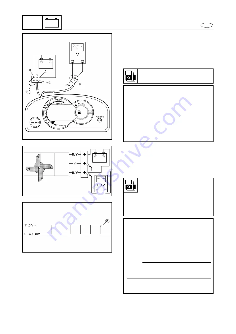
Speed meter output voltage:
10.5 V
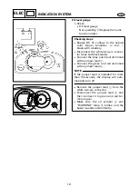
Checking steps:
●
Supply DC 12 voltage to the natural
color six-pin connector (+: red, –:
black) with a battery.
●
Connect the green and red terminals
with a jumper lead
1
.
●
Measure the voltage on the speed sen-
sor connector (white color three-pin
connector) between the red/white and
black leads.
Speed sensor output voltage
(dependant on the paddle wheel
position):
Less than 400 mV/
More than 11.6 V
Output pulse:
2 pulses/one-full turn
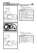
Checking steps:
●
Apply DC 12 voltage to the white color
three-pin connector (between the red/
yellow and black/yellow leads).
●
Rotate the paddle wheel by hand and
measure the voltage between the
black and yellow leads.
NOTE:
As the paddle wheel is rotated, a square-
wave voltage signal
a
is produced.
●
Two pulses occur every time the pad-
dle wheel makes one-full turn.


