8-30
E
HULL
HOOD
HOSES
HOSES
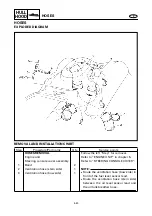
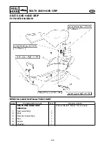
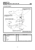
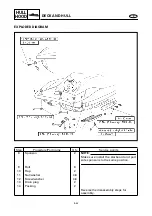
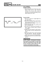
EXPLODED DIAGRAM
REMOVAL AND INSTALLATION CHART
Step
Procedure/Part name
Q’ty
Service points
HOSES REMOVAL
Follow the left “Step” for removal.
Engine unit
Refer to “ENGINE UNIT” in chapter 5.
Steering console cover assembly
Refer to “STEERING CONSOLE COVER”.
1
Band
2
2
Ventilation hose (stern side)
1
NOTE:
●
Route the ventilation hose (bow side) in
front of the fuel level sensor lead.
●
Route the ventilation hose (stern side)
between the oil level sensor lead and
the oil tank breather hose.
3
Ventilation hose (bow side)
1


