2-8
SPEC
E
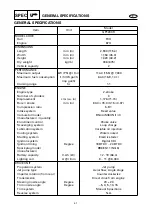
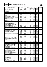
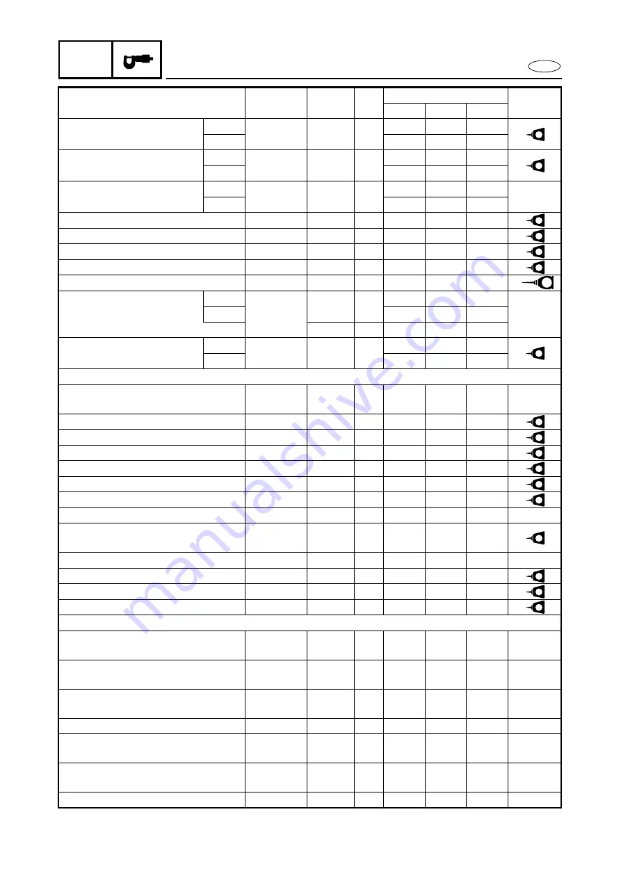
TIGHTENING TORQUES
Cylinder – crankcase
1st
Bolt
M10
12
22
2.2
16
572
LT
2nd
39
3.9
28
Generator cover –
crankcase
1st
Bolt
M10
7
15
1.5
11
271
LT
2nd
50
5.0
36
Generator cover/ground
lead – crankcase
1st
Bolt
M10
1
15
1.5
11
2nd
50
5.0
36
Bracket – crankcase
Bolt
M10
4
39
3.9
28
271
LT
Pickup coil – generator cover
Bolt
M5
2
5
0.5
3.6
242
LT
Stator coil – generator cover
Bolt
M6
3
15
1.5
11
242
LT
Drive coupling – crankshaft
Coupling
M27
1
36
3.6
25
572
LT
Flywheel magneto – crankshaft
Bolt
M10
1
75
7.5
54
E
Upper crankcase – lower
crankcase
1st
Bolt
M8
17
15
1.5
11
2nd
27
2.7
19
M6
10
11
1.1
8.0
Engine bracket – lower
crankcase
1st
Bolt
M8
6
15
1.5
11
271
LT
2nd
27
2.7
19
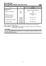
JET PUMP UNIT
Steering cable joint – nozzle
deflector
Nut
—
1
7
0.7
5.1
Ride plate – hull
Bolt
M8
4
17
1.7
12
572
LT
Intake duct – hull
Bolt
M8
4
17
1.7
12
572
LT
Intake grate – hull
Bolt
M6
4
7
0.7
5.1
572
LT
Nozzle ring – nozzle
Bolt
M8
2
15
1.5
11
271
LT
Nozzle deflector – nozzle ring
Bolt
M8
2
15
1.5
11
271
LT
Strainer cover – impeller duct
Bolt
M6
4
7
0.7
5.1
572
LT
Drive shaft nut – drive shaft
Nut
—
1
74
7.4
53
Impeller (left-hand threads) –
drive shaft
Impeller
—
1
18
1.8
13
572
LT
Transom plate – hull
Nut
—
4
26
2.6
19
Intermediate housing – bulkhead
Bolt
M8
3
17
1.7
12
572
LT
Driven coupling – shaft
Coupling
—
1
36
3.6
25
572
LT
Speed sensor – jet pump cover
Screw
—
4
4
0.4
2.9
242
LT
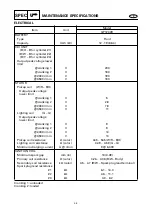
HULL AND HOOD
Handlebar cover – handlebar
cover stay
Screw
M6
4
1.1
0.11
0.8
Handlebar cover stay – steering
column
Screw
M6
4
2.9
0.29
2.1
Upper handlebar holder/lower
handle holder – steering column
Bolt
M8
4
16
1.6
11
QSTS converter – hull
Nut
—
2
5
0.5
3.6
Throttle lever assembly –
handlebar
Screw
M5
2
3
0.3
2.2
Handlebar switch assembly –
handlebar
Screw
M5
2
3
0.3
2.2
QSTS grip assembly – handlebar
Screw
M6
1
3
0.3
2.2
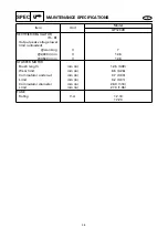
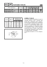
Part to tightened
Part name
Thread
size
Q’ty
Tightening torque
Remarks
Nm
m•kgf
ft•lb


