2-23
E
SPEC
CABLE AND HOSE ROUTING
B
D
C
15˚
15˚
B
A
D
C
1
2
3
Ñ
È
A
É
Ê
Ë
Ï
Î
Î
Ï
Í
Ì
Ð
Ô
Ó
Õ
Ö
×
Ø
Ù
Ú
Û
Ï
Ï
Ò
Ü
20˚
Ð
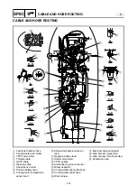
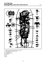
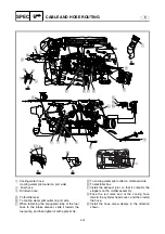
Contact the corrugated tube to the hose screw
clamp (muffler assembly end).
Ñ
Strongly pull the plastic tie.
Ò
After installing the YPVS servomotor, fasten the
throttle cable.
Ó
Fasten the exhaust temperature sensor lead.
Ô
To cylinder #1
Õ
To cylinder #2
Ö
To cylinder #3
×
Cooling water inlet
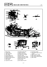
Ø
Install the white tape end of the negative battery
lead to the battery.
Ù
Fasten the sub-wire harness and wire harness
(generator).
Ú
Fasten the wire harness (generator).
Û
Route the sub-wire harness under the cooling
water hose.
Ü
Install the oil pump cable to the angle shown in
the illustration.
Summary of Contents for WaveRunner GP1300R
Page 1: ...SUPPLEMENTARY SERVICE MANUAL GP1300R WaveRunner F1G 28197 1G 1X LIT 18616 02 90 LIT186160290...
Page 10: ...E TROUBLE ANALYSIS TROUBLE ANALYSIS 48 SELF DIAGNOSIS 48 WIRING DIAGRAM...
Page 61: ...YAMAHA MOTOR CORPORATION USA Printed in USA Dec 2004 0 0 1 CR E...
Page 62: ...SERVICE MANUAL GP1300R WaveRunner F1G 28197 1F 11 LIT 18616 02 44 LIT186160244...
Page 340: ...YAMAHA MOTOR CORPORATION USA Printed in USA Feb 2003 0 0 1 CR E...


