6-20
E
JET
PUMP
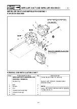
BEARING HOUSING
SERVICE POINTS
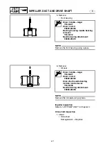
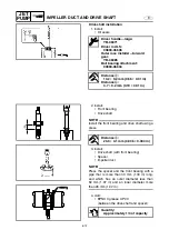
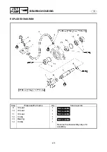
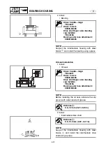
Driven coupling removal and installation
1. Remove and install:
• Driven coupling
NOTE:
Install the driven coupling with the same spe-
cial service tools that were used for removal.
T
R
.
.
Driven coupling:
36 N • m (3.6 kgf • m, 25 ft • lb)
LOCTITE 572
Coupler wrench:
YW-06551/90890-06551
Shaft holder:
YB-06552
Crankshaft holder 20:
90890-06552
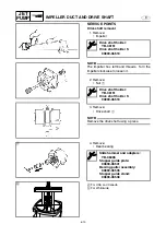
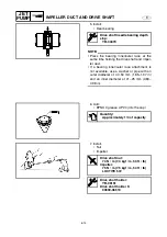
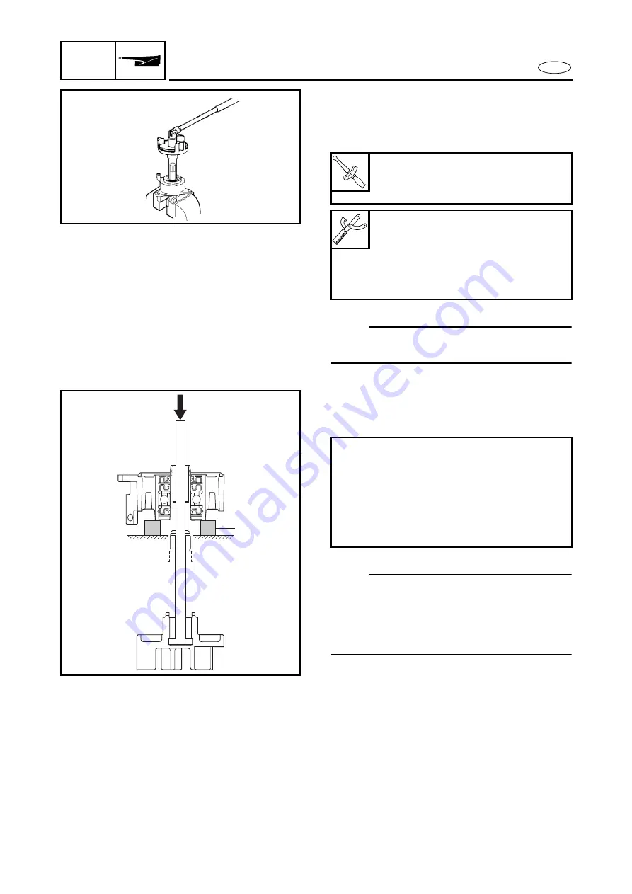
Intermediate drive shaft removal
1. Remove:
• Intermediate drive shaft
NOTE:
Support the intermediate housing with steel
blocks
1
and press the intermediate drive
shaft with a rod that is more than 280 mm
(11.02 in) long, and which has an outer diame-
ter less than 13 mm (0.51 in).
Removal steps:
• Temporarily install the driven coupling to
the intermediate drive shaft.
• Insert a long rod to the intermediate drive
shaft.
• Press out the intermediate drive shaft by
pushing the rod.
1
Summary of Contents for WaveRunner GP1300R
Page 1: ...SUPPLEMENTARY SERVICE MANUAL GP1300R WaveRunner F1G 28197 1G 1X LIT 18616 02 90 LIT186160290...
Page 10: ...E TROUBLE ANALYSIS TROUBLE ANALYSIS 48 SELF DIAGNOSIS 48 WIRING DIAGRAM...
Page 61: ...YAMAHA MOTOR CORPORATION USA Printed in USA Dec 2004 0 0 1 CR E...
Page 62: ...SERVICE MANUAL GP1300R WaveRunner F1G 28197 1F 11 LIT 18616 02 44 LIT186160244...
Page 340: ...YAMAHA MOTOR CORPORATION USA Printed in USA Feb 2003 0 0 1 CR E...

